Technical Insights · Machine upgrades

ACE Engineering GroupTechnical Insights
Pantograph luffing: from boom moment to cylinder force
Follow the load path through a pantograph arrangement and understand why counterweight changes affect more than cylinder force.
General technical information. Obtain engineering advice for your machine before applying it. Read the article disclaimer.
Follow the load path, not just the cylinder force.
This symbolic example considers static gravity loads at one luff position. It is a teaching guide, not a project assessment.
A counterweight adjustment can restore the calculated cylinder force while the centre link and support loads remain different. Check those effects as part of the complete machine assessment.
Illustrative analysis
Pantograph reclaimer: luff cylinder force
Static balance at one luff position, with the cylinders connected to the counterweight assembly.
Read the calculation steps and assumptions
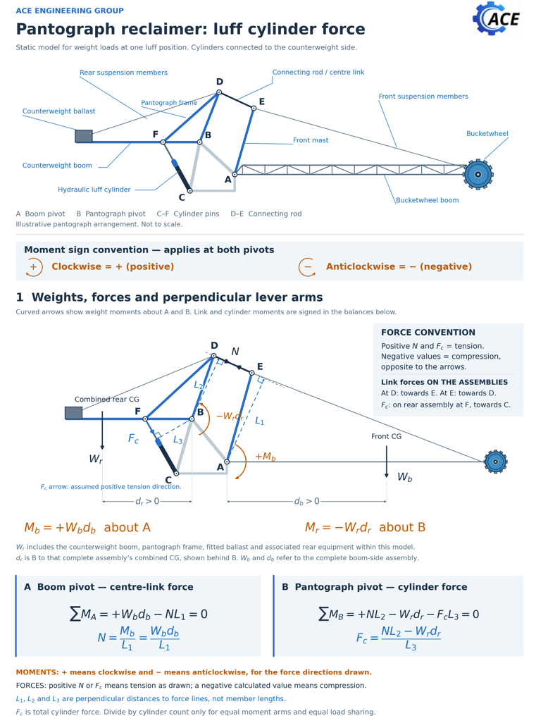
A is the boom pivot and B is the pantograph pivot. C to F are the cylinder pins; D to E is the connecting rod or centre link. Clockwise moments are positive at both pivots.
Wb and db describe the complete boom side assembly. Wr includes the counterweight boom, pantograph frame, fitted ballast and associated rear equipment in this model; dr locates that assembly’s combined centre of gravity behind B. Use weight and centre of gravity from the same configuration.
- Boom balance about A
+Wbdb − NL1 = 0
N = Mb / L1 = Wbdb / L1
N is the actual centre link axial force.
- Pantograph balance about B
+NL2 − Wrdr − FcL3 = 0
Fc = (NL2 − Wrdr) / L3
Positive N and Fc mean tension for the directions drawn; negative results mean compression. L1, L2 and L3 are perpendicular distances to force lines, not member lengths. Fc is total cylinder force. Divide by cylinder count only for equal moment arms and equal load sharing.
Added counterweight to retain the original cylinder force
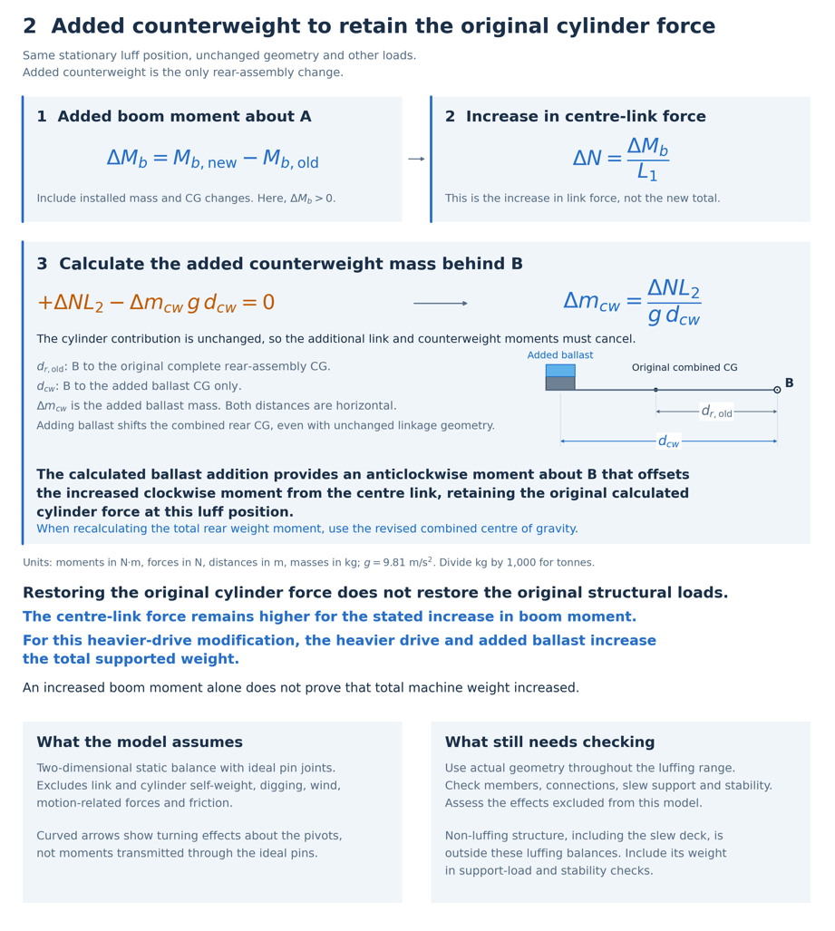
At the same stationary luff position, with unchanged geometry and other loads:
ΔMb = Mb,new − Mb,old
ΔN = ΔMb / L1
Δmcw = ΔNL2 / (g dcw)
Here dcw is the horizontal distance from B to the added ballast’s centre of gravity. It is not the distance to the original combined rear centre of gravity. Added ballast is the only rear assembly change in this calculation. Recalculate the combined rear centre of gravity when checking the revised total balance.
Restoring the calculated cylinder force does not restore the original centre link force or supported weight.
Model assumptions
Two dimensional static weight balance with ideal pin joints at one luff position. Link and cylinder self weight, digging, wind, motion related forces and friction are excluded. The diagram is not to scale.
Use the actual geometry through the full luff range. Check connected members, connections, slew support and stability, including non luffing structure outside these balances. Assess the loads excluded from this model.
Moments are in N·m, forces in N, lengths in m and masses in kg; g = 9.81 m/s². The example uses symbols only, with no project specific values.
Apply the example within its limits.
The guide excludes digging, wind, inertia and friction. An actual machine requires its geometry, load cases, complete luff range and stability to be assessed.
Read about weight savings and counterweightBack to ACE’s engineering approach
Start a conversation
Planning a machine upgrade?
Discuss the proposed change, the machine configuration and the structural or mechanical support required.
Keep learning
More technical insights from ACE.
Register your interest in future engineering articles and occasional workshop invitations.