
Define the complete lighter arrangement
One tonne removed near a bucketwheel has a different gravity moment from one tonne removed near the slew centre. Their contributions to rotational inertia also differ. Begin with an added and removed mass schedule, including the centre of mass of every changed item. A percentage reduction in plate thickness is not a finished machine mass saving.
Include reinforcement, brackets, services, guards and access added by the revised arrangement. Reducing a maintenance platform may be worthwhile if servicing and removal space remain adequate. Refining chute geometry requires the required material flow, wear provisions and access to be preserved. Define those functions before counting the saving.
Treat the first mass estimate as a design opportunity. It becomes a supported option only when the affected members, connections, equipment interfaces and manufacturing requirements are defined. Otherwise the project may price a lighter concept and purchase a heavier detailed solution.
Find what controls the thickness
Higher strength steel can permit less material where yield resistance governs. Its elastic modulus is essentially unchanged. Reducing thickness changes section properties, plate slenderness and connection flexibility, so deflection, buckling or fatigue may prevent the proposed reduction.
Consider a hypothetical welded box chord with unchanged outside dimensions and a proposed thinner wall. The revised member may satisfy a yield check while becoming more flexible where a brace transfers load into the chord face. Establish the local load path and stress range before accepting the saving. Retaining thickness locally or revising the connection may be useful; the steel added back belongs in the mass schedule.
For conventional classified welded details, higher parent steel strength does not automatically increase fatigue resistance. The IIW recommendations state that their welded joint fatigue curves are independent of material tensile strength within the limits of static strength considerations. [1, section 3.2] The applicable detail, stress range, thickness effects and fabrication quality still need assessment. Qualified weld treatment may provide a useful improvement, subject to its detail, loading and execution limits. Treatment at the weld toe does not establish the adequacy of an untreated root. [1, section 3.5.3]
CIDECT Guide 8 distinguishes member force analysis from the local stress concentrations around hollow section joints. [2, sections 3.1 to 3.5] Apply a method suited to the actual geometry and its validity limits; do not assume a thinner chord preserves the original connection performance because the gross member force has fallen. Reinforcement terminations also need fatigue assessment. For circular hollow section T joints, CIDECT advises locating side plate ends in relatively uniform stress regions to limit adverse notch effects. [2, section 6.2.3(b)]
| Potential governing requirement | Effect of thinner material | Evidence needed |
|---|---|---|
| Yield resistance | Higher grade may offset reduced area | Revised member and connection resistance |
| Stiffness and movement | Section stiffness can fall | Deflections, clearances and relevant dynamic response |
| Buckling | Slenderness and imperfection sensitivity can change | Applicable local and overall stability checks |
| Fatigue | Local stress range and detail performance can change | Compatible fatigue method, detail and duty |
| Manufacture and service | Welding, handling and retained condition can govern | Buildable detail, inspection and corrosion provisions |
One tonne off the boom could mean three off the machine
Take a simplified example of a new reclaimer in the illustrated position. Assume all other masses and positions remain unchanged.
The net one tonne saving is centred at the bucketwheel, 50 metres horizontally from the slew bearing centreline. The counterweight blocks are centred 25 metres horizontally from the same centreline, on the opposite side.
The corresponding counterweight reduction is:
1 tonne × 50 m ÷ 25 m = 2 tonnes.
That identifies a potential three tonne reduction in the superstructure, subject to the full machine assessment. In this position, the opposing reductions leave the existing net gravity moment at the slew bearing unchanged.
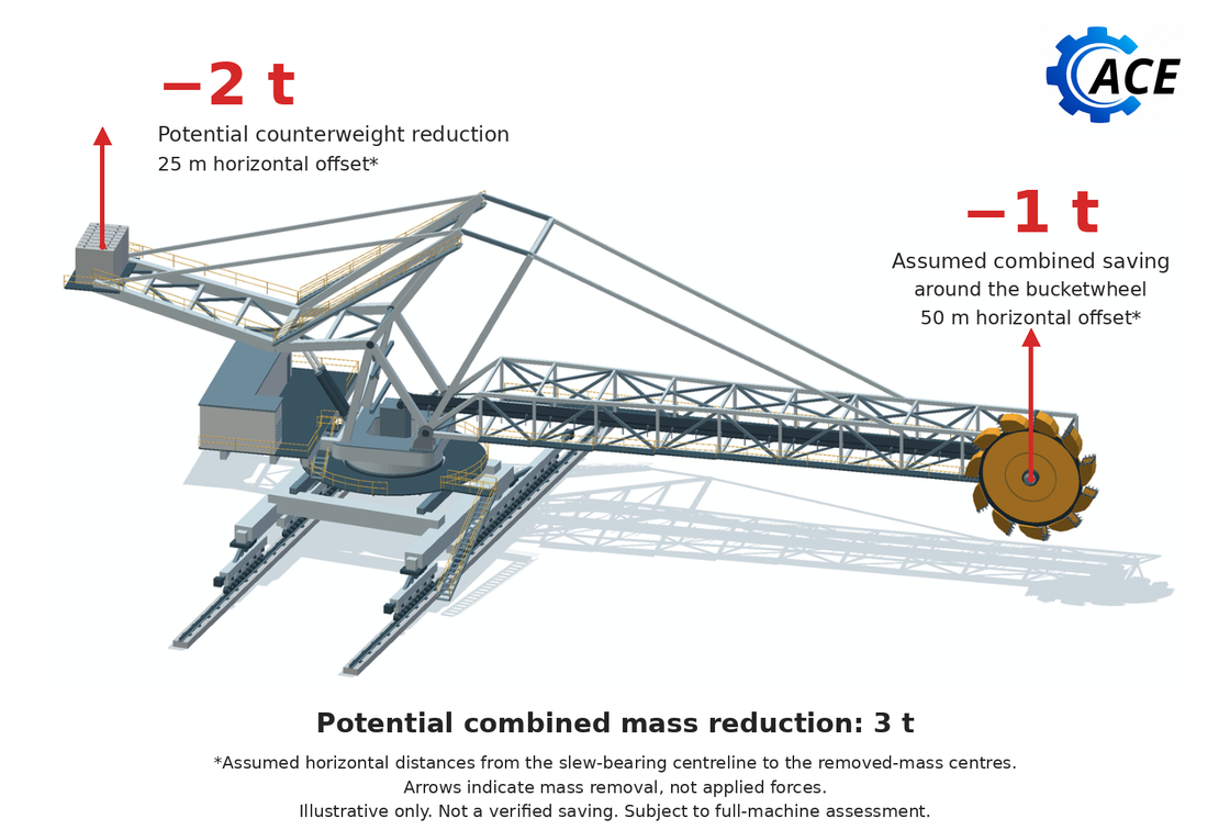
The location matters. Savings spread along the boom must be included at their actual positions. One tonne removed closer to the slew bearing would not produce the same result.
This calculation does not tell us the force in the luff cylinders or connecting rods. Those forces depend on the actual pivot, link and cylinder positions. Check the complete arrangement before removing any counterweight.
Carry the option through the machine
Assess the actual mechanism through relevant luff and slew positions, material states, wind conditions and maintenance stages. Define the balance objective: acceptable cylinder demand, bearing actions, wheel reactions and overturning stability are related but separate checks. A favourable result at one angle cannot establish every other condition.
Where the design credits a surviving cylinder or another restraint after a fault, check the required response with the revised mass distribution. Include the associated asymmetric actions. Changing a relief or control setting to accommodate a lighter arrangement needs its own hydraulic and structural assessment.
In the example, the bearing and lower structure receive three tonnes less total superstructure dead mass. Individual wheel reactions do not necessarily fall equally. Preserving the moment about the slew centre while reducing weight can lower the highest support reaction while bringing another support closer to uplift. The actual support geometry, equalisation and load case determine the result. Durst and Vogt discuss stability at both the superstructure and travel supports, and the consequences of adding or removing heavy components. [3]
Removing mass away from the slew axis reduces the mass moment of inertia about that axis. Under the same prescribed angular acceleration, the associated inertial torque falls. Actual drive, brake and fatigue benefits depend on the complete actions, control response and operating cycle. Do not convert a percentage mass saving directly into a percentage fatigue or maintenance benefit.
Changes to thickness and mass distribution can also alter natural frequencies and dynamic response. Screen the revised arrangement against operating excitation and control actions, and undertake further analysis where a material risk is identified. Lower reactions at driven or braked wheels can reduce available traction or braking where wheel and rail friction governs.
Keep the installation and maintenance states in the assessment
An arrangement can work when complete yet become unacceptable while a drive, chute or counterweight is removed. Establish the removal sequence, temporary supports and restraint requirements before claiming that a lighter component is simpler to install. Confirm the retained structure can carry each temporary configuration.
WA Mines Safety Bulletin 128 recommends current balance information when designing alterations and a balance check before work that can affect stability. [4] Its stacker incidents concern isolation and uncontrolled movement; they do not establish a universal ballast adjustment procedure. For an existing machine, compare the proposed configuration with verified mass, condition and modification records.
Price only benefits that the design can deliver
First screen the net mass reduction, its effect on the governing requirement and the likely cost range. If the benefit is too small to justify development, stop or revise the concept. Develop shortlisted options far enough to resolve the governing checks and obtain meaningful quotations.
Obtain quotations for the actual grades, thicknesses, plate sizes and quantities, with certification and delivery requirements. Purchasing minimums, cutting yield, welding procedures, qualification, distortion control and inspection can change the cost. Avoid treating nominal steel price per tonne as the fabricated cost.
Include engineering, detail development, revised drawings, interfaces, temporary works, installation and commissioning. Credit a smaller bearing, drive or foundation only when the option changes its required selection and the associated cost. Until that work is established, record the benefit as an opportunity rather than a saving.
For a new machine, there may be value in developing a lighter arrangement before procurement. For an existing machine, access and shutdown work can outweigh a modest material reduction. Compare technically adequate options against the agreed duty and service life, separating installation cost, production consequences and future maintenance assumptions.
The decision record should state the net mass and location changes, justified ballast adjustment, governing checks, affected interfaces and quoted scope. Identify uncertainties that could reverse the result. ACE can assess those consequences together so the OEM and fabricator price an achievable arrangement, rather than a mass target that the final detail cannot meet.
References
[1] Hobbacher A (2008). Recommendations for Fatigue Design of Welded Joints and Components. IIW-1823-07, sections 3.2 and 3.5.3.
[2] Zhao XL and colleagues (2000; printing 2001). Design Guide for Circular and Rectangular Hollow Section Welded Joints under Fatigue Loading. CIDECT Design Guide 8, sections 3.1 to 3.5, pp. 26 to 28, and section 6.2.3(b), p. 54.
[3] Durst W and Vogt W (1988). Bucket Wheel Excavator. Series on Mining Engineering, volume 7. Chapter 7, printed pp. 229–233.
[4] Department of Mines and Petroleum, Western Australia (2015). Mines Safety Bulletin 128: Isolation issues with rail-mounted stackers. Printed pp. 2–3. Read source