
Establish whether the comparison is valid
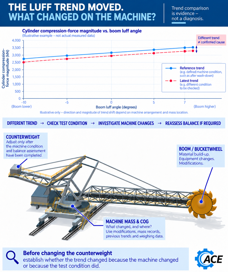
Suppose a reclaimer has a higher luff pressure than recorded at its previous balance test. Adding counterweight appears attractive because it may bring the pressure closer to the earlier value. That decision is premature until the two tests describe comparable conditions.
If the agreed reference is an empty machine after washdown, residual material on the boom changes the test. Its effect depends on where the material sits. Permanent ballast added to compensate remains after the next thorough clean, when the temporary material load has gone.
Record fitted equipment, retained material, conveyor load, travel position, slew position and boom angle. Establish machine inclination, including relevant rail slope and cross level, and record wind conditions. Use a defined reference condition or account for differences that could affect the comparison. Durst and Vogt discuss the influence of inclination and external forces, and specify calm conditions for the weighing method they describe. [1]
Record oil temperature, whether the hydraulic system has warmed up, the direction of the last movement and the settling period. Readings after raising and lowering may differ through friction and hydraulic behaviour; moving traces also contain dynamic effects.
For the calculation of cylinder force from chamber pressures and its limitations, see the article on luff cylinders and control limits.
Obtain hydraulic review where pressures remain unexplained
Higher pressure in one chamber does not establish a higher external load. Compare both chamber pressures under the defined test conditions before interpreting the change as a balance problem.
Have the hydraulic designer establish whether the readings are consistent with the intended circuit behaviour and identify any hydraulic issue before ballast or settings are changed. The review should address load holding, stopping and relevant transient behaviour against the machine’s design requirements.
| Possible explanation | Evidence to compare | Decision affected |
|---|---|---|
| Different test condition | Machine and material condition, travel and slew positions, boom angle, inclination and wind | Repeat under the reference condition or account for the differences |
| Permanent mass change | Installed and removed equipment, locations and independent weighing information | Update the mass model and assess any balance adjustment |
| Hydraulic behaviour | Both chamber pressures, oil temperature, movement history and circuit state | Obtain hydraulic review before interpreting unexplained pressures as a balance change |
| Measurement uncertainty | Calibration, zero, repeatability and uncertainty in the calculated force | Establish whether the observed change can be resolved |
Use the linkage that the machine actually has
Cylinder force becomes a useful balance indicator when related to the actual mechanism. A directly supported boom and a pantograph arrangement have different force relationships. Cylinder lines of action change with position, and the boom, mast, connecting rods and counterweight assembly may move differently.
Use equilibrium of the connected parts, or a suitable virtual work formulation, with the actual geometry and mass locations. Comparing opposing gravity moments about a horizontal axis through the slew bearing centre can describe a global moment at one position. It does not, by itself, calculate luff cylinder force. Use each component’s actual pivots and force paths.
The same cylinder force can hide a higher centre link load
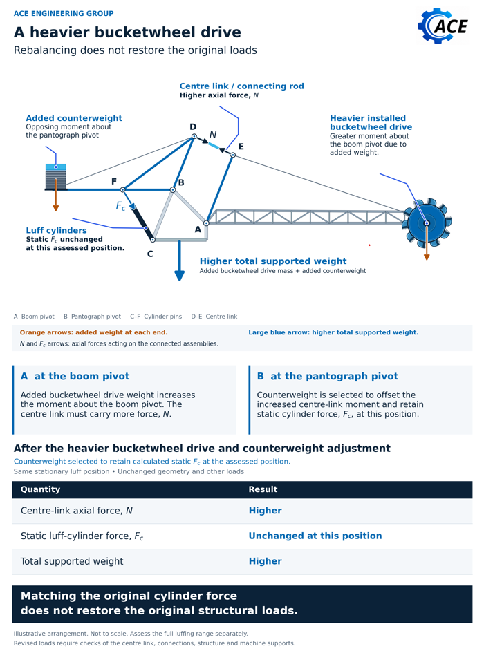
Consider a pantograph arrangement in which a centre link connects the bucketwheel boom to a separately pivoted counterweight assembly. Compare the same stationary luff position, with unchanged geometry and other loads. A heavier drive adds a weight moment about the bucketwheel boom pivot.
If the centre link supplies the balancing moment on that boom, an unchanged perpendicular lever arm means the added weight moment requires more link force. Include the drive supports and all other additions or removals at their actual locations.
A counterweight addition can provide an opposing moment on the separate assembly. An appropriate adjustment may restore the cylinder force at that position while the centre link retains its increased load. Both added masses remain on the machine.
This result depends on the stated load path. It cannot be transferred to every luffing arrangement. Agreement at one position does not establish agreement through the luff range. Check the centre link, its end connections, boom, pivots and cylinder supports using the revised force system.
Reconcile the mass model with independent evidence
A model fitted to a luff curve can suggest changes consistent with the measurement. Several combinations of mass and location may produce similar curves, especially over a limited angular range. An inferred trim mass is a modelling parameter until independent evidence establishes a physical change.
Use equipment records, surveys and weighing to constrain the interpretation. Durst and Vogt discuss weighing to verify calculated mass and centre of gravity, and the need to consider stability when heavy components are added or removed. [1] Equipment on a slew deck that does not luff can change total mass and support reactions without a corresponding change in the cylinder curve.
Their weighing discussion states: “The accuracy of the results, however, is dependent on the method used.” [1, page 232] Define which loads the measurement captures, account for other external actions and establish measurement uncertainty. Rail level weighing can constrain overall reactions and projected centre of gravity in the measured configuration. It does not alone establish every component mass, centre of gravity height or untested load case.
Vibration and recurring alarms may help identify when behaviour changed. They are not specific to imbalance. Keep hydraulic faults, friction, instruments and mechanical condition in the investigation until the evidence distinguishes them.
Accept the revised machine configuration
Define the acceptable cylinder force envelope from the machine design or a documented reassessment. Carry the revised configuration through relevant luff and slew positions, loaded and empty states, operating and parked wind cases, and maintenance conditions. The previous test curve is a diagnostic reference; acceptance requires the applicable force limits and other machine checks.
Assess component strength, relevant fatigue effects, slew bearing loads, wheel reactions and overturning stability under the applicable design basis. Include support contact and uplift where relevant. Durst and Vogt distinguish stability at the superstructure support from stability at the machine travel supports, and consider changes with machine position. [1] Use the actual support arrangement and acceptance criteria for the machine.
Include applicable fault conditions, such as load transfer after a cylinder failure. Define the required response, such as stopping, emergency holding or controlled recovery. Determine the surviving cylinder demand and any asymmetric structural action from that sequence. An adjustment favourable in one condition can be less favourable at another position or during a fault.
Check that protection settings remain consistent with the assessed structural and hydraulic limits. Schmidt and van Rensburg’s stacker case involved underestimated loading, deficient connections and bolts, and inadequate protection, including an overload alarm set too high. The case demonstrates why control limits and structural capacity must be assessed together. [2]
The acceptance record should explain the measured difference, identify the mass and hydraulic assumptions retained, and compare resulting demands with the applicable limits. Resolve uncertainties that could change the decision before accepting the adjustment.
After approved work, verify installed masses and locations, repeat the defined balance measurements and complete the weighing or functional tests required by the assessment. Record the accepted baseline and revised limits. WA Mines Safety Bulletin 128 recommends current balance data when designing alterations and a balance check before work that may affect stability. [3]
ACE can assess how a changed luff trend relates to the machine configuration and define the linkage, structural and stability checks needed before changing counterweight.
Sources
[1] Durst, W. and Vogt, W. (1988). Bucket Wheel Excavator. Series on Mining Engineering, volume 7. Trans Tech Publications. Chapter 7, printed pp. 229 to 233; weighing discussion p. 232.
[2] Schmidt, M. J. and van Rensburg, B. W. J. Avoiding structural failures on mobile bulk materials handling equipment. Journal of the Southern African Institute of Mining and Metallurgy, volume 115, March 2015, pages 179 to 184. Stacker case on pages 181 to 182; recommendations on page 184. Read source
[3] Department of Mines and Petroleum, Western Australia. Mines Safety Bulletin 128, Isolation issues with rail mounted stackers. 25 November 2015, pages 2 to 3. Available through WorkSafe WA. Read source