When a stacker boom moves without warning
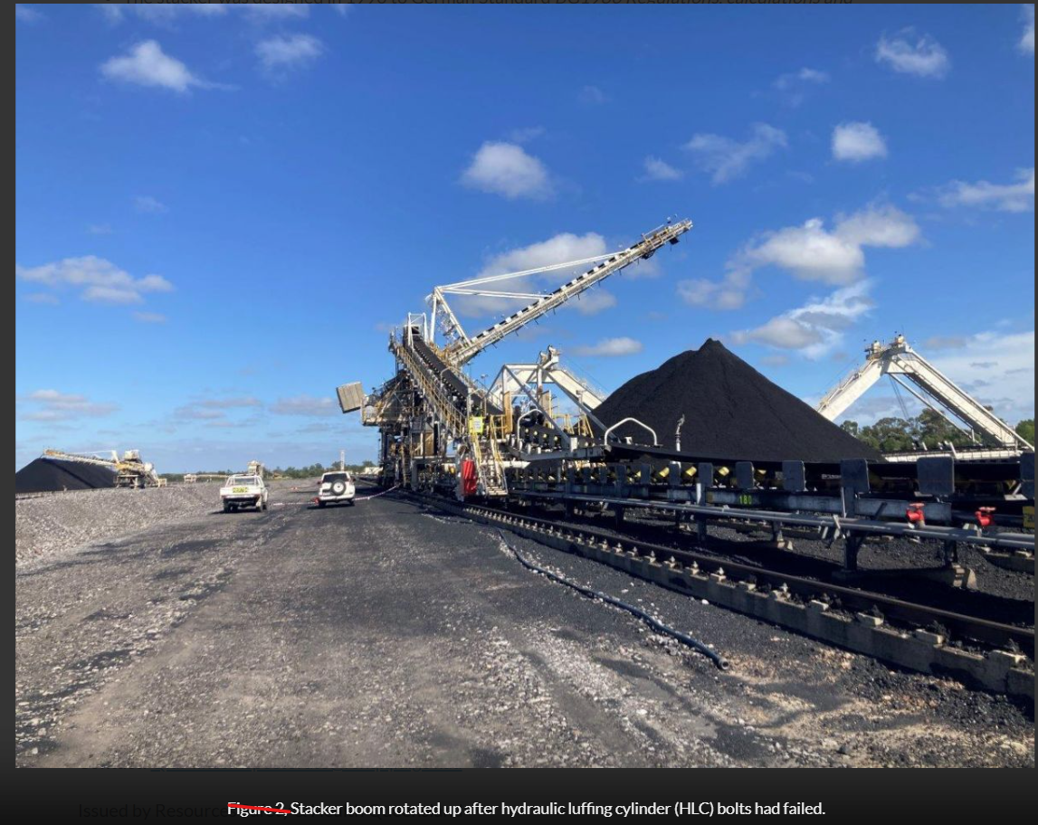
A Queensland coal stacker was lowering into position when its boom suddenly rose. A worker was onboard, but no one was injured. The safety alert, published on 12 May 2025, reported that the hydraulic cylinder had detached at its lower clevis connection. The counterweight then drove the boom upwards. Preliminary observations identified worn bolts and stripped nut threads; the investigation was ongoing when the alert was issued. [1]
The cylinder did not need to burst for restraint to be lost. Failure at its attachment interrupted the path holding the boom. That is why a cylinder assessment must include the rod, pins, clevises, bolts, lugs, welds and supporting steel.
Why a walkway inspection can miss the problem. A connection can look sound while deterioration is concealed at a pin, bush, thread or bearing surface. External checks remain useful, but they cannot establish the condition of every assembled joint. Plan shutdown inspections around critical connections, using dimensional checks, disassembly and appropriate non destructive testing where needed.
Unexpected relative movement may reveal clearance or looseness. Observe it only through a controlled method with suitable exclusion arrangements and remote measurement where appropriate. Intrusive inspection needs isolation and engineered support; personnel should not approach a suspect loaded connection to look for movement.
Why a single support path matters. If the only effective restraint fails, the boom can move under the remaining weight imbalance. The direction and extent depend on the machine’s balance, position and other restraints. A second cylinder can provide emergency support only when it, its connections and the surrounding structure can withstand the load transfer and remain effective.
Holding after a failure is also different from lowering safely or continuing production. WA Mines Safety Bulletin 128 describes uncontrolled stacker movement during maintenance and issues with hydraulic holding and relief settings. The required held condition and recovery method need to be established for the actual machine. [2]
Why older machines need review. The Queensland machine was designed in 1990 to BG1986. [1] For existing machines, Clause 1.2 of AS 4324.1:2025 places evaluation within a risk assessment for continued use, upgrade or modification. [4] Assess the present condition and duty. Inspection and maintenance remain essential, but they do not create a surviving load path where none exists.
Load sharing in a dual cylinder system
A dual cylinder system must maintain the load distribution allowed for in the design and provide the required support after one cylinder fails. Both functions depend on the cylinder arrangement, its connections, the hydraulic circuit and the supporting structure.
An anonymised reclaimer example from the author’s experience illustrates the load sharing issue. Production was repeatedly interrupted by differential cylinder force alarms. The machine was boom heavy and the cylinders carried high tensile loads. One cylinder often carried more than the other. At first, the alarms appeared to be a production nuisance.
Raising the threshold reduced trips. It did not remove the uneven loading. The machine’s balance explained the high overall demand, but did not by itself explain why the two cylinders carried different forces. That distinction matters when deciding what to fix.
Check the combined force and how it is shared. The total force is the force carried by both cylinders added together. Load sharing describes how much of that total each cylinder carries. One cylinder can take more while the other takes less, leaving the total unchanged. This can increase local attachment loads and twist the supporting frame.
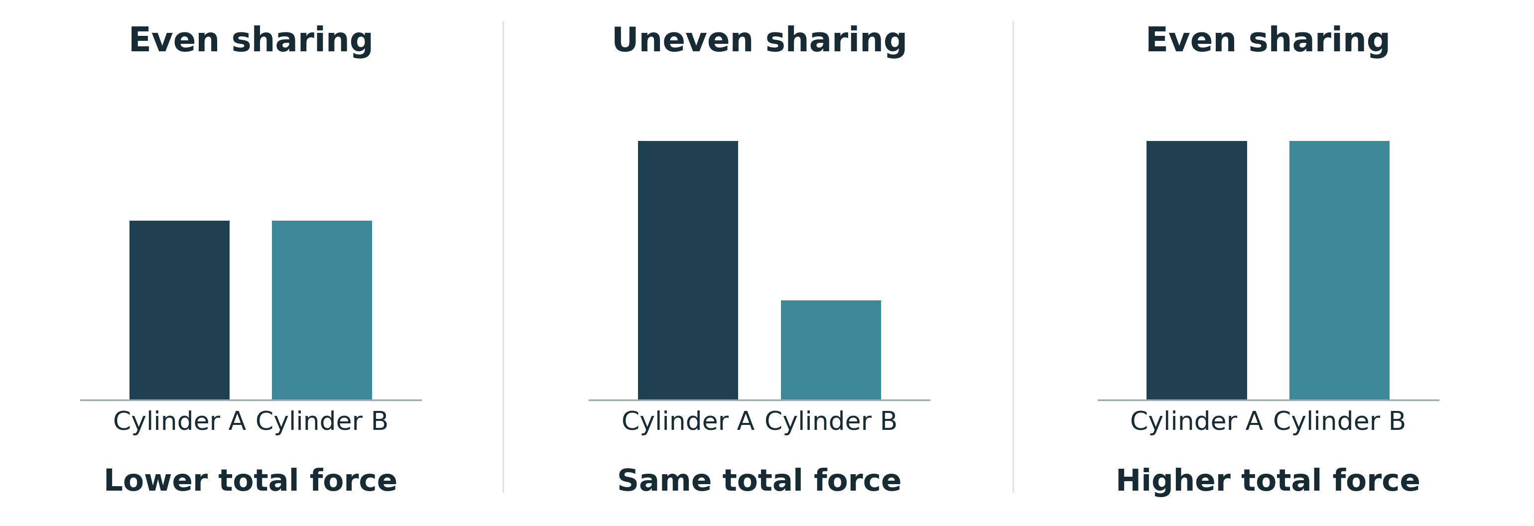
If both cylinder forces rise together by the same amount, their difference stays the same while the total increases. An alarm based only on that difference may therefore miss excessive total demand. Check each cylinder force and the combined force against the assessed limits for that machine and operating condition.
The fatigue issue is the changing stress at the lugs, welds and surrounding steel. Repeated changes in the force split can increase local stress ranges even when the structure passes a peak load check. A steady imbalance alone does not establish fatigue damage; the assessment needs the stress history, number of cycles and resistance of the detail.
A differential force alarm should prompt investigation. Confirm whether it reflects real unequal loading, hydraulic behaviour, friction, alignment, structural movement or measurement error. Raising its threshold or extending its delay may allow a greater difference to develop before stopping. Fewer trips demonstrate less interruption; they do not demonstrate an acceptable load history.
Check the forces behind the alarm
Pressure readings only help if they are converted into force correctly. For a cylinder with one piston rod, pressure acts on different areas on the two sides of the piston. Both chamber pressures are needed. [3]
The cap side pressure acts on the full piston area. The rod side pressure acts on the smaller area around the rod, producing an opposing force. Each chamber’s force is its pressure multiplied by that effective area.
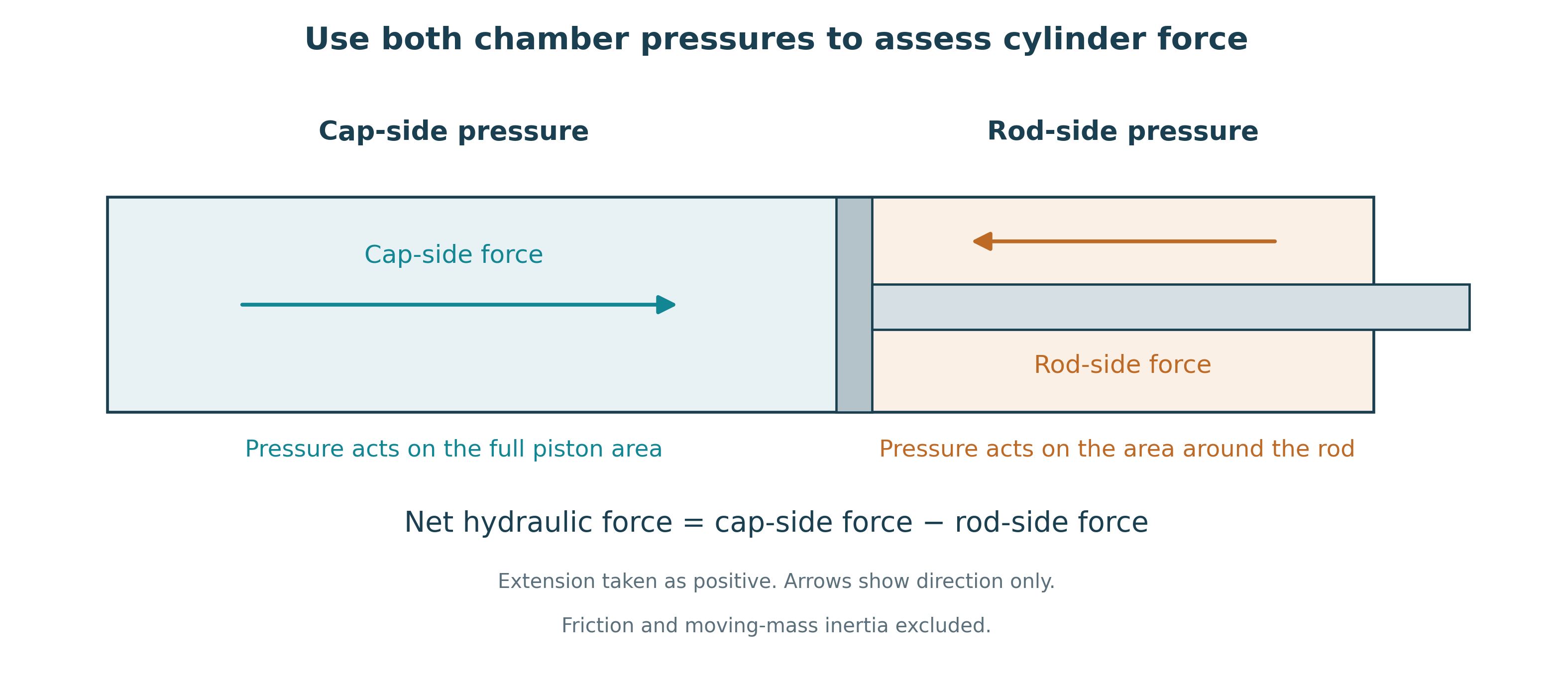
Calculate each cylinder separately. Confirm dimensions, sensor location, calibration, range and synchronised readings, then relate the results to boom position, loading and movement. Equal pressure in one chamber does not prove equal cylinder force. A sensor trace that reaches its measurement limit cannot establish the true peak.
The trip setting must allow justified normal variation while stopping the machine before unacceptable demand develops. Include measurement uncertainty, setting tolerance and the load that can develop during the stopping response. If those requirements leave no usable setting range, changing the number in the controller will not resolve the problem.
The remedy follows the cause. It may involve correcting hydraulic behaviour or alignment, restoring the intended machine balance, changing the operating duty, or strengthening a fatigue prone detail. Inspect the pins, lugs, welds and brackets where the assessment identifies high demand. Reinforcement alone does not correct an unresolved load sharing problem.
Small details still matter: a poorly assembled fitting, an unsuitable weld detail or a valve with inadequate capacity can undermine the intended protection. For a shiploader, stacker or reclaimer with serious failure consequences, redundancy must be judged by the verified response of the complete system, not by the number of cylinders purchased.
Applying the cylinder requirements
AS 4324.1:2025 sets requirements for hydraulic cylinder support systems. Clause 5.7.7 prohibits single hydraulic cylinder support systems in tension or compression and requires the structure and cylinders to be assessed with one cylinder failed. The failed luff cylinder case is an Extra Load, with its load combinations defined in the technical specification under Appendix B. [4]
The standard’s commentary identifies 2017 as the edition that added Clause 5.7.7. The 2025 edition adds explicit compression cylinder buckling requirements while retaining the failed cylinder assessment. [4, Clause A.119]
| Cylinder action | Capacity used in the factor | Normal dual system | After one cylinder fails |
|---|---|---|---|
| Tension | Ultimate cylinder tensile capacity provided by the supplier | 4 | 2 |
| Compression | Calculated ultimate buckling capacity of the cylinder assembly | 4 | 2 |
For compression, the buckling factor is the calculated cylinder buckling capacity divided by the applied load: at least 4 in the normal double cylinder case and 2 after one cylinder fails. Use an established method in a recognised standard; Clause 5.7.7 gives DNV ST 0194 and EN 13001 3 6 as examples. These factors are not pressure setting multipliers or permission to continue operating after failure.
Apply the factor to the assessed load in each cylinder, including unequal sharing. Do not assume that each cylinder always carries half the total load.
The design response should satisfy the cylinder requirements and remain compatible with the complete machine. Where a larger cylinder is selected, review its mass, mountings, pins, brackets, hydraulic requirements and maintenance access. Include any associated counterweight or structural changes in the design scope, installation plan and cost estimate.
On a stacker with boom side cylinders, additional cylinder and attachment mass may increase the boom side moment and require a counterweight adjustment. On a reclaimer with cylinders located at the counterweight boom, additional mass may increase that side’s weight without adding counterweight blocks. Actual locations, geometry and mass distribution govern the result; neither arrangement describes every machine.
Stability and counterweight. Recheck the balance strategy and stability for the relevant operating and failure conditions. Adding ballast can solve one balance condition while worsening another demand.
Slew bearing and supports. Carry changes in vertical load, overturning moment and linkage forces through the pivot, slew bearing, supports and substructure.
Strength and fatigue. Check the steelwork, welds and critical joints for the revised loads and stress history. Some machines may need larger members or stronger connections. A larger cylinder does not automatically increase fatigue damage, but the previous assessment cannot simply be assumed to cover the changed machine.
Select a design solution for the governing condition
Establish the governing load cases and component checks, then select a solution that satisfies the applicable standard and operating requirements. Cylinder buckling, attachment strength and operating demand need separate consideration.
If cylinder buckling governs, assess the complete assembly over its extension range, including actual end restraint, alignment and side loading. Better restraint or support may improve capacity, but its stiffness, clearances and behaviour throughout the stroke must be demonstrated. Added guidance can introduce side loads or prevent the required articulation.
If the connection governs, consider local stiffening or revised pins, lugs and brackets. Check pin bending, bearing, welds and load transfer. Changing lug spacing may improve the connection; it does not automatically reduce the cylinder’s effective buckling length.
If operating demand governs, investigate balance and duty before increasing component capacity. A larger bore does not reduce the force needed to hold the same load at the same geometry. It changes the required pressures and the force available at existing pressure settings. It also changes the relationship between oil flow and cylinder speed, so valves and response need review.
The surviving cylinder check must include load transfer, asymmetric attachment demand, frame torsion and any movement or impact. Define the failure being assessed and establish whether it could also disable the surviving support through a shared hydraulic, control or structural element.
When a luff limit starts governing the machine
In an anonymised operating example from the author’s experience, the boom occasionally stopped lowering during heavy reclaim. The luff system had reached its limit and operation resumed when the load reduced. No obvious structural defects had been identified. From the outside, the machine appeared unchanged.
The interruption looked like a control setting getting in the way of production. Increasing the limit appeared to offer a simple improvement. But that limit was also defining which operating conditions the machine could continue to experience.
Later operating data indicated that loads were approaching the upper range assumed in the original design and suggested that machine balance had changed over time. The proposal therefore needed a review of the machine’s operating duty, not just a check of available cylinder pressure. Before attributing a trend to changed balance, compare readings at equivalent boom positions and operating conditions, then check the relevant mass and geometry.
With a higher limit, the boom may spend longer in heavily loaded operation, pass through more demanding cycles or reach higher peaks. Even if the maximum load stays the same, the frequency and pattern of loading can change. Time near maximum pressure is not itself a fatigue calculation; translate the operating history into the stress ranges and cycles experienced by the structure.
Check what happens before the machine stops
Identify the function being changed. A total force trip, differential force trip, pressure relief and luff angle limit do different jobs. The assessment needs the actual setting, filtering, delay, valve response and stopping action. Clause 3.1.2 of AS 4324.1:2025 addresses loads limited by protective devices; Clause 3.5.16 gives the corresponding requirements for Extra Loads. [4]
Schmidt and van Rensburg’s stacker investigation identified connection deficiencies, defective bolts and inadequate protection with an overload alarm set too high. [5] That case reinforces the need to check both the physical load path and the settings intended to protect it.
Before increasing a limit, establish the existing balance and operating loads, compare the proposed duty with the design assumptions, and assess the resulting stress history and stopping response. Record the protection settings in the structural calculations and operating and maintenance manual, together with the required action on activation. Verify during commissioning that the installed settings and response match the assessed basis. Where a control function prevents overload, establish its required reliability and failure response with the control specialist.
A machine can look the same and pass the same visual inspection while operating under a different load history. Any resulting fatigue problem may appear at a lug, weld or substructure connection far from the controller. Changing the limit is an engineering change to the machine.
The decision must cover the whole machine
Inspection helps detect deterioration. A verified surviving support can limit the consequences of failure. Correct load sharing and suitable controls keep operating demand within the assessed limits. None of these replaces the others.
AS 4324.1:2025 provides requirements for cylinder capacity and the failed cylinder condition. Applying those requirements involves the complete support system. Assess each cylinder for its actual load and demonstrate that the surviving support remains effective after the defined failure. Check changes to cylinder size or operating limits against machine balance, structural demand, operating duty and stopping response. The calculations, approved settings and verified machine response should remain traceable to the accepted design basis.
ACE assesses the structural and mechanical design alongside the hydraulic and control evidence to support a coordinated solution for the complete machine.
References
[1] Resources Safety & Health Queensland (2025). Uncontrolled movement of coal stacker boom. Coal Inspectorate Alert No. 456 V1, 12 May. NSW Resources Regulator (2025). Quarterly safety report April to June 2025, p. 13. Source Related source
[2] Department of Mines and Petroleum, Western Australia (2015). Isolation issues with rail-mounted stackers. Mines Safety Bulletin 128, 25 November, pp. 1–3. Source
[3] HAWE Hydraulik. Fluidlexikon: Piston. Accessed 15 October 2026. Source
[4] Standards Australia (2025). AS 4324.1:2025 Mobile equipment for continuous handling of bulk materials — Part 1 General requirements for the design of steel structures. Published 24 October. Clauses 1.2, 3.1.2, 3.5.16 and 5.7.7; Tables 5.7 and 5.7.7 (printed p. 60); normative Appendix B; informative Clause A.119 (p. 94). Source
[5] Schmidt MJ and van Rensburg BWJ (2015). Avoiding structural failures on mobile bulk materials handling equipment. Journal of the Southern African Institute of Mining and Metallurgy 115, pp. 179–184; stacker case pp. 181–182. Source