Set the design basis using AS 4324.1
AS 4324.1:2025 expressly includes slew bearing replacement under maintenance loads in Clause 3.4.11. Load combination II/4 in Tables 3.7(A) and 3.7(B) covers maintenance. Clause 6.4 requires the technical specification to define the loads and load cases for major maintenance and its associated equipment. Use the factors for the selected design method, and check other conditions relevant to the work. [10]
The Standard also addresses jacking points directly. Normative Appendix B, Table B.1, requires the technical specification to define jacking point requirements, including allowances for variation in the machine’s as built balance and centre of gravity. Informative Appendix A, A.127, specifically identifies jacking eccentricity and temporary supports for slew bearing changes. [10]
Engineering judgement is needed to turn these requirements into a support design and work method for the actual machine. The assessment must establish the loads, check the supporting steel and restraints, and define the conditions under which the arrangement can be used.
Confirm the machine configuration for the change out
Confirm the boom and slew positions to be used during the work. Identify equipment that will remain on the machine, material left on the belts or structure, temporary equipment and components that will be removed. Use this information to establish the machine’s weight and centre of gravity for each stage. These are needed to calculate the support loads and check stability.
Check whether the existing jacking drawings apply to these conditions. They may have been prepared for a different machine position or an earlier equipment arrangement.
Added steel, replacement equipment and material build up can change the machine’s weight and balance. Repairs can change stiffness, and distortion can affect the bearing support ring. Normal operation does not demonstrate that the temporary jacking arrangement remains suitable.
Clause 5.9 of AS 4324.1:2025 requires verification of mass and centre of gravity after construction. It also applies when modifications significantly affect mass, centre of gravity, stability or balance. Use current records and suitable measurements to establish the condition being assessed; do not assume the original design values still apply. [10]
Compare the jacking pads and supporting steel with the drawings. Check their condition, previous repairs and access to critical welds. Confirm the loads each detail was designed to carry. A thick plate is not proof of a suitable jacking point. Previous successful use does not confirm that it can carry a different load or work with a changed support arrangement.
Durst and Vogt describe raising the upper structure on jacks to unload the slew bearing for inspection or replacement. They also explain a limitation when using jack loads to estimate the structure’s weight: the bearing must be fully unloaded, and all the relevant weight must pass through the measured supports. Their examples do not establish the capacity of an existing jacking point. [2]
Check how the load transfers between supports
Do not assume each jack will carry an equal share of the weight. This can underestimate the load on the most heavily loaded jack. Load sharing depends on where the supports are placed, their starting levels, how much the upper and lower structures bend, and how the hydraulic system operates.
A support cannot carry load until it makes contact with the structure. Equal hydraulic pressure and equal jack movement do not necessarily mean equal loads. Select the controls and measurements to match the load sharing assumed in the engineering assessment.
The table summarises the conditions to check. It is not a lifting procedure. The approved method must set the actual sequence and identify the checks required before work proceeds.
| Stage | What needs to be checked | Evidence needed |
|---|---|---|
| Load begins to transfer | Which jacks are carrying load, and what remains on the bearing? | Support levels, contact, measured loads and permitted limits |
| Bearing disconnected | What carries the weight and prevents sideways movement or tipping? | Separation checks, support loads and restraints |
| Lift for bearing removal | Is there enough clearance throughout the lift and removal route? | Measured clearances, jack travel and movement checks |
| Machine on temporary supports | Will the machine remain supported and stable throughout the work? | Holding arrangement, wind limits, monitoring and response plan |
| Load returned to bearing | Can load be returned without binding or damaging the bearing? | Accepted mounting surfaces, alignment and transfer checks |
Check the steelwork around each jack
Check both ends of each jack. At the top, follow the force through the contact plate, internal stiffeners, webs and welds into the upper structure. At the base, follow it through the lower supporting steel to the undercarriage, rails or temporary foundation. Check the whole load path, including details hidden behind the visible jacking pad.
Allow for the jack being placed off centre or at an angle. An offset or horizontal force at the jack head can bend a pad or web that was checked only for a centred vertical load. Specify where the jack must sit, the permitted offset and any horizontal load to be carried. Confirm that the crew can achieve and measure the required positions.
A spherical seat allows a limited amount of angular movement. It does not remove every problem caused by an offset or sideways load. Figure 1 shows why the jack position matters, even when the applied force is unchanged.
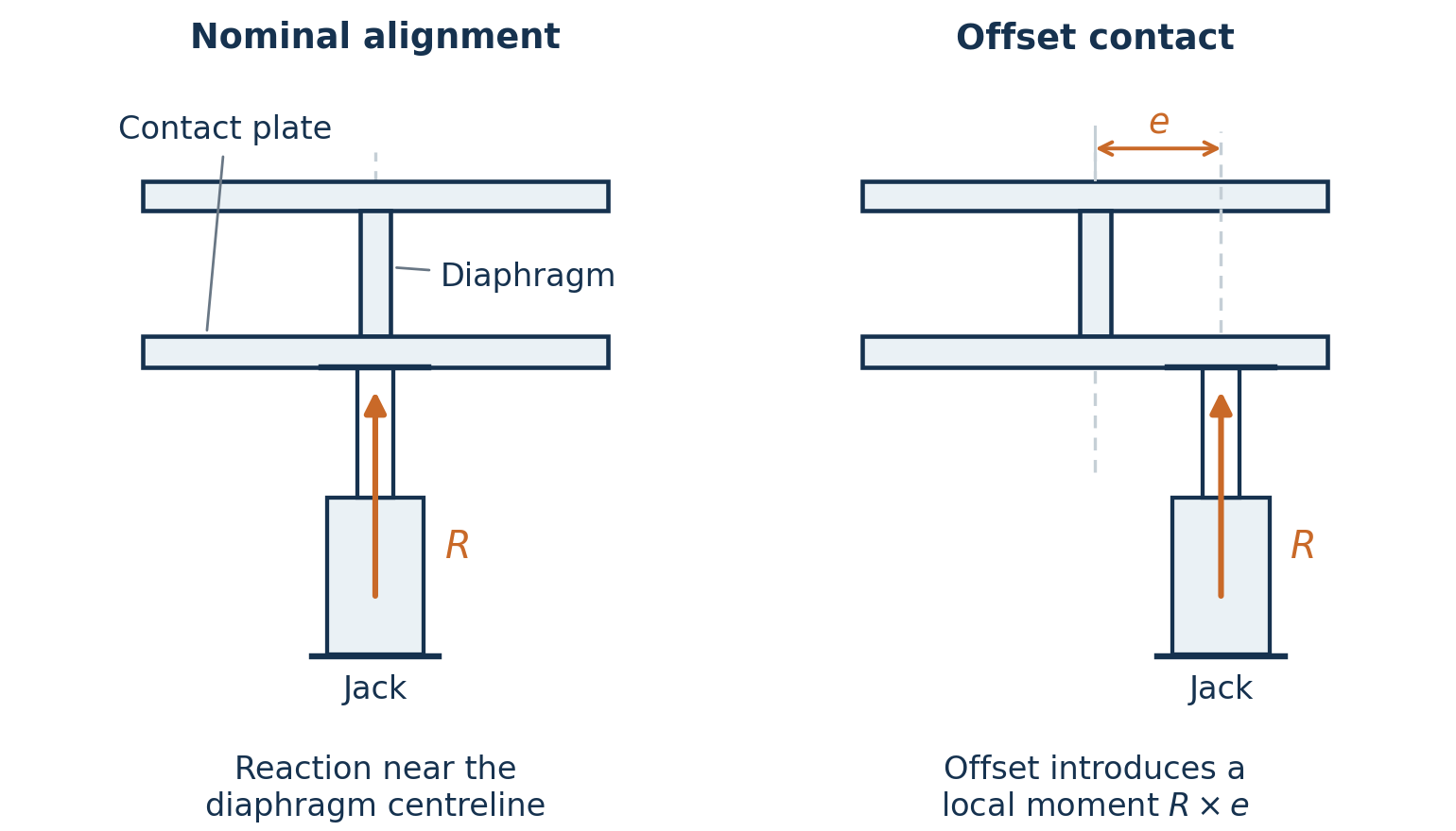
Check the jack at the extension needed for the lift, using its actual support conditions and the supplier’s limits. Do not assume the jack head can stop sideways movement. If a restraint must carry horizontal force, check its connections and the structure receiving that force. [3]
Check how much the steelwork can bend during the lift. Pad bending can tilt a jack, shift load to another support or distort the bearing seat. Set limits that preserve stable support and allow the new bearing to be installed correctly. Any proposed acceptance of permanent deformation needs a specific engineering assessment. Stop and obtain engineering review if movement or deformation exceeds the assessed limits.
Establish a working load limit for each jacking point and state the conditions that apply to it. Include the machine position, load direction, permitted jack offset and any restrictions during lifting or holding. The jack’s rated capacity does not establish the capacity of the supporting steel. The work method must keep the loads and movements within the assessed limits.
Keep the machine stable throughout the change out
Check stability at two levels:
- The lifted upper structure must remain stable on its jacks and temporary supports.
- The whole machine must remain stable on its travel supports, such as wheels or crawlers.
A support underneath the structure can carry weight, but it may not prevent the structure from lifting off or moving sideways. Include any restraints needed to prevent these movements in the support design.
For the whole machine, apply the overturning checks in Clause 4.1 of AS 4324.1:2025, including the required stability ratios and each possible tipping axis. Check the lifted upper structure separately using its actual temporary supports and restraints. [10]
Assess wind loads for the entire time the machine will be on temporary supports. The lift may be brief, but bearing removal and repairs can leave the machine supported for several days. Allow for delays, and consider wind from different directions.
Clause 3.4.11 requires the machine to be secured against movement caused by wind, with wind speeds determined using AS/NZS 1170.2. If the maintenance design uses wind loading below the Standard’s idle wind load, WW, the technical specification must define it. A brief lifting period alone does not justify reducing the wind load for the whole change out. [10]
Specify when lifting must stop and what wind conditions the machine can withstand while it remains supported. Define the actions required if the weather worsens, allowing enough time to carry them out. Once the bearing is removed, lowering the machine back onto it may no longer be possible. The plan must therefore explain how the machine will remain stable in that condition. Stopping work alone does not remove the wind load.
Also prevent unexpected movement of the boom and other assemblies during maintenance. Do not rely on trapped hydraulic pressure alone to hold them in place. WA Bulletin 128 describes incidents where hydraulic isolation failed to prevent movement. [4] Identify how each assembly could move, including under its own weight, and provide the restraints and isolation measures needed for the work. [5]
Plan how to hold the load and respond to a jack failure
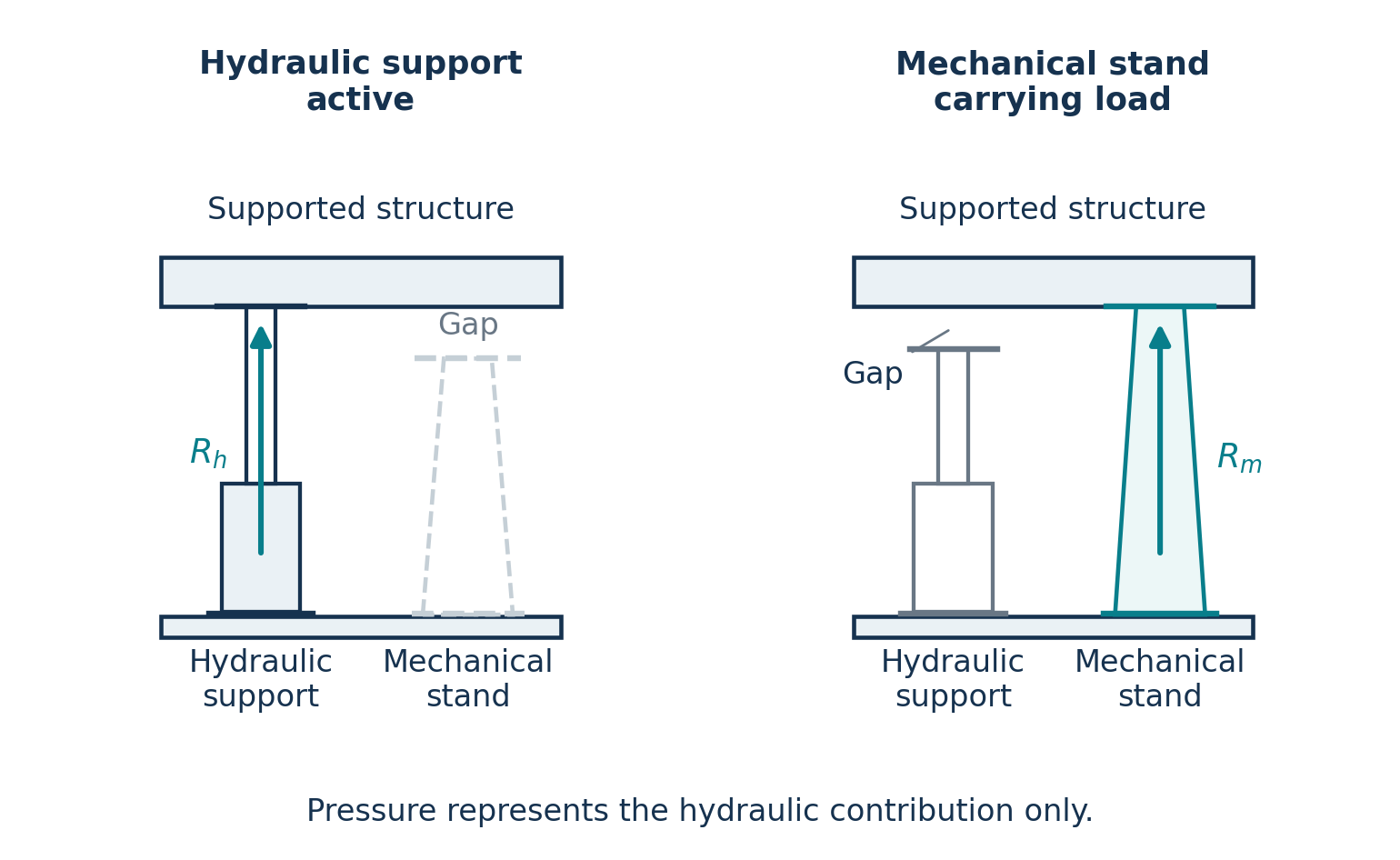
Steel stools with packer plates have been used beside hydraulic jacks as a mechanical backup against unintended lowering if a jack seal, pump or hydraulic line fails. Shah’s maintenance guide illustrates this arrangement. [6]
Plan how the load will move between the hydraulic jacks and mechanical supports. Check that the stools, packers and supporting steel can carry the load and remain stable. Verify the mechanical holding condition before personnel work under or near the load, in accordance with the selected equipment instructions. [3]
Some client technical specifications require duplicate jacks at each jacking point. Where this applies, check that one jack can carry the required load at that point while the other is unavailable. Assess the remaining jack, its contact with the structure, the changed load position, the supporting steel and the hydraulic connections.
Also assess what happens if a jack fails unexpectedly. Check how the load shifts and whether the remaining supports keep the machine stable. A shared hose, valve or structural detail can leave both jacks vulnerable to the same failure. Duplicate jacks do not automatically replace mechanical supports or locking devices.
Holding the load after a failure, transferring it to another support and continuing to lift are different tasks. An arrangement that can hold the load after a failure may not allow further lifting.
If there is a gap above a standby support, the structure may drop before that support takes the load. Assess the forces caused by that movement as well as the load after the structure comes to rest.
Define how the load will remain supported while a jack is adjusted or removed. Check that the required blocks, locks or alternate supports can be installed and inspected at that stage of the work.
Check removal clearance and the bearing mounting surfaces
An arrangement may fit while the machine is parked but clash as the upper structure rises. For example, a projecting lug or bracket may hit a cross member before there is enough clearance to remove the bearing. The jacks and pads may be strong enough, but the collision still prevents removal. Continuing to lift can put load through parts that were not designed to carry it.
Check clearances through the full lift and along the bearing removal route. Allow for the structure to bend under load, and confirm that the jacks have enough travel. Check the space needed for mechanical supports, hoses, tools and the bearing itself.
Resolve access changes before the shutdown. Leave enough room to inspect and, if necessary, machine the bearing mounting surfaces after the old bearing is removed.
The steel structures above and below a slew bearing must be stiff enough to spread the loads around the bearing. If they bend unevenly, some parts of the bearing can carry more load than intended. Rothe Erde explains this relationship and recommends measuring the mounting surfaces before installation, with repairs or machining where required. Use the actual bearing supplier’s requirements to decide whether the surfaces are acceptable. [7], [8]
When measuring the bearing mounting surfaces, record how the machine is supported and what loads it is carrying. The steelwork may bend differently on jacks than it does in service. This can change the flatness readings.
Agree how to account for that temporary bending before accepting the surfaces or deciding to machine them. Check flatness under the support and loading conditions specified by the bearing supplier. Separately, assess how the supporting steel will bend under operating loads. Passing a flatness check on jacks does not prove that the new bearing will be adequately supported in service. [9]
Give the shutdown team clear limits and checks
The work method should state the machine position, expected support loads, permitted jack positions and movement limits. Include wind limits and the response to equipment failure. Identify who checks that supports are carrying load, that the bearing is free and that clearances are adequate. State who can authorise the next stage and what must happen if measurements fall outside the agreed limits.
Choose instruments with suitable ranges and calibration, and explain how their readings will be used. Hydraulic pressure can help estimate jack force, but the calculation must account for the effective piston area, friction and hydraulic arrangement. Once a mechanical stand or locknut carries load, pressure alone cannot show the total load at that support. Monitoring checks whether the machine behaves as expected; it does not replace the support assessment.
Define the checks and records needed before returning load to the new bearing and restarting the machine.
The jacking arrangements can become the limiting part of a bearing change out. Give those points the same attention as the bearing, and resolve their capacity, stability and access requirements before the shutdown. ACE can assess the temporary supports and work with the owner and maintenance contractor to coordinate the lifting, measurement and bearing installation requirements.
References
[1] Department of Mines and Petroleum WA (2013). Mines Safety Bulletin 103, Failure of maintenance jacking points on stackers, reclaimers and shiploaders during replacement of slew bearings, 22 January. Source
[2] Durst W and Vogt W (1988). Bucket Wheel Excavator. Series on Mining Engineering, volume 7. Chapter 7, pp. 229–233, p. 232.
[3] Enerpac. Core Cylinders Operation and Maintenance Manual, L4787 revision C, sections 1, 3.4, 4.8 and 5.1.4. Source
[4] Department of Mines and Petroleum, Western Australia (2015). Isolation issues with rail-mounted stackers. Mines Safety Bulletin 128, 25 November, pp. 1–3. Source
[5] Work Health and Safety Commission, Western Australia (2022). Managing risks of plant in the workplace. Code of practice, section 4.5, pp. 53–54. Source
[6] Shah, K. P. (2019). Construction, Working and Maintenance of Stackers and Reclaimers for Bulk Materials, March edition, pp. 39–41. Source
[7] thyssenkrupp rothe erde. Technical basics: Companion structure. Accessed 15 October 2026. Source
[8] thyssenkrupp rothe erde. Technical basics: Measurement and machine processing of the contact areas. Accessed 15 October 2026. Source
[9] Kaydon (2016). How mounting can optimize slewing ring bearing performance, PDF pp. 2–4. Source
[10] Standards Australia (2025). AS 4324.1:2025, Mobile equipment for continuous handling of bulk materials, Part 1: General requirements for the design of steel structures. Clauses 3.4.11, 3.7, 4.1, 5.9 and 6.4; Tables 3.7(A) and 3.7(B); informative Appendix A, A.127; normative Appendix B, Table B.1. Relevant printed pages: 29, 41–49, 61–63, 96 and 103.