Conveyor drive support column corrosion
A shiploader inspection found significant cracking in previously repaired flange bolted connections in the support columns. From the outside, the machine appeared sound: the paint was intact and there was no visible distortion. The repaired connections had not been inspected since the earlier work.
On the same shiploader, targeted non destructive testing of the conveyor drive support columns revealed substantially more section loss than expected. The internal surfaces of the pulley support columns had never been accessed for inspection. These surfaces could not be examined from the walkway, and arranging scaffolding was difficult and time consuming.
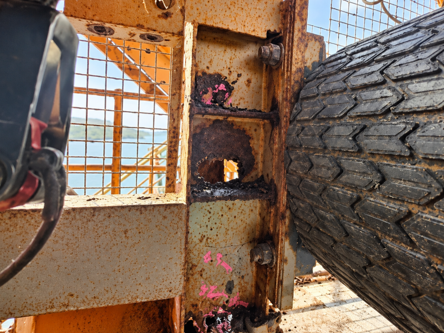
The damage required extensive repairs and put the machine out of service for weeks. The cracking and section loss were separate findings; their presence alone does not prove that corrosion caused the cracks.
The practical sequence is to establish the condition, reassess what it means for continued operation, and turn the findings into timely repair and follow up. Corrosion can change the basis of every step.
Corrosion changes the basis of the fatigue assessment
A fatigue assessment depends on the detail, loads, material, environment and condition assumed. Unchanged production duty does not preserve that assessment if corrosion has changed the section or exposure. Both fatigue and corrosion can be assessed, but the earlier basis must be checked against the condition now present.
Section loss increases demand on the remaining steel. For the same axial force over the same width, a thinner section carries higher membrane stress. Loss near a weld, bolt group or load entry can also change local bending, stiffness and load transfer.
Pitting creates local stress concentrations. A pit can provide a site for fatigue initiation. Its depth, shape and location matter; an average thickness can conceal a much more severe local condition.
Corrosive exposure can affect crack progression. Environmental effects can accelerate fatigue crack growth, depending on material, exposure and loading. The IIW baseline fatigue resistance assumes non corrosive conditions with normal atmospheric protection. It should not be carried unchanged into an actively corroding detail without justification. [4]
A simplified, hypothetical calculation illustrates section loss. Reducing a uniformly thinned plate strip from 10 mm to 7 mm, with axial force and width unchanged, raises calculated membrane stress by 10/7, about 43%. This is not a fatigue life prediction or acceptance limit. Pitting, bending, buckling, load redistribution and a crack require separate assessment.
Past crack behaviour does not guarantee the next interval
Fatigue cracks need not grow at a constant rate, even without corrosion. Growth depends on the crack size and geometry, stress range, material and environment. As a crack extends, its driving force can increase even when the applied load is unchanged. [6] A period of little measured change therefore does not establish years of remaining service.
Active corrosion, a deeper crack or changed loading can make an earlier growth estimate unsuitable. The practical risk is losing the planned intervention window. Check comparable measurements and reassess progression rather than extending an old trend indefinitely. Visible rust or surface crack length alone cannot establish the growth rate or remaining life.
Static strength does not establish fatigue life
A static strength check addresses the assessed load and condition. Fatigue assessment addresses repeated loading and damage over time. A detail can satisfy a static check while still requiring action for fatigue. Neither assessment has a universal margin that makes the other unnecessary.
Where a crack already exists, assess its extent, sizing uncertainty, remaining resistance and credible progression. A calculation for an initially uncracked detail does not establish whether that crack can remain in service. Completing a weld repair does not automatically reset the detail’s fatigue life.
Make the inspection capable of finding the relevant damage
The assessment needs evidence from the critical locations. Paint, retained material, weld geometry and poor access can conceal damage. Record close examination, partial coverage and areas not examined separately. An external walkdown cannot establish the condition of an inaccessible internal surface.
Select non destructive testing with an inspection specialist. Ultrasonic thickness measurements can establish remaining section at measured locations. Magnetic particle or eddy current methods can assist surface or near surface crack detection, subject to material and procedure. Select the method for the material, defect and examination requirements. [7] Ultrasonic crack examination, including phased array where suitable, needs a procedure matched to the geometry and required sizing.
Define preparation, coverage, location references and reporting requirements. A few spot thickness readings can miss local pits; a surface crack indication does not establish its full depth. The report must show what was actually examined and the limitations of the result.
Give repaired connections and actively corroding fatigue critical areas appropriate priority based on consequence, condition and uncertainty. Recover repair records and examine the installed detail and adjacent load transfer. Cracking after a repair may be remaining damage, renewed initiation or cracking elsewhere; the cause must be established.
Plan access as part of the work: rope access, scaffolding, elevated work platforms or designed hatches and removable panels, as appropriate. Book the access and examination together. Repeatedly carrying an inaccessible critical area into the next report leaves the condition unresolved.
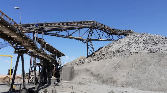
The 2019 WA fixed conveyor stacker incident demonstrates the consequence of corrosion and inadequate inspection access. The regulator identified substantial corrosion of critical members, retained product and shortcomings in inspection and access. [1] It is a corrosion related structural failure example; the report does not establish corrosion fatigue as its cause.
Reassess the operating decision as condition changes
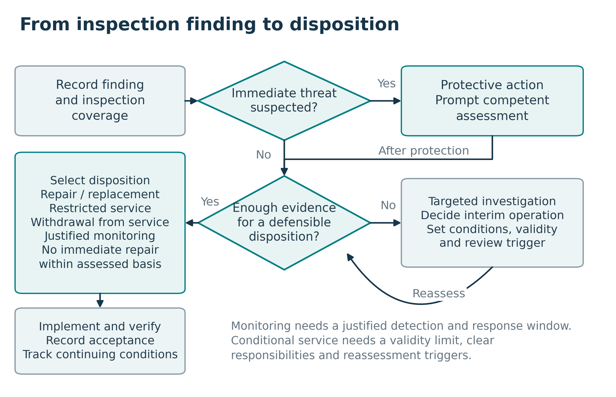
The acceptable risk criterion does not become less demanding because deterioration has increased. If damage progresses faster than assumed, or the examination leaves greater uncertainty, the existing plan may no longer demonstrate acceptable risk. Reassess operating conditions, inspection scope and repair timing against the established criteria; do not assign a numerical failure probability from appearance alone.
Use the findings to decide on continued operation, restrictions or withdrawal. Where the operating basis is in doubt, obtain engineering review and implement necessary interim controls promptly. WA’s Mines Safety Bulletin 124 calls for protective measures where structural strength or reliability is inadequate. [2] Action need not wait for the final report.
Check whether another load path can actually carry the load
Redundancy can reduce the consequence of a local defect only where an alternative path can carry the redistributed load. Check the connections, remaining capacity and stability in the damaged condition. Adjacent members exposed to the same corrosion may not provide the assumed reserve. Where no effective alternative exists, a missed critical defect can have severe consequences.
Use risk based inspection and leave time to act
Risk based inspection (RBI) uses the likelihood and consequence of failure to set priorities, then selects methods, coverage and intervals for the relevant damage. For this shiploader, repeat cracking, observed corrosion and section loss, and unexamined critical surfaces warrant attention. Lack of access is an uncertainty to resolve, not evidence of low risk. Reduce effort on lower risk details only with a documented basis and retain required examinations.
Where assessment supports continued operation under defined conditions, set monitoring intervals from the mechanism, condition, duty, uncertainty and response time. Review priorities after each inspection, repair or duty change. An annual date alone is insufficient; a shorter interval helps only if the damage can be detected and action completed in time.
Track each crack and thickness location against a baseline using comparable methods. Record coverage, preparation and uncertainty, together with relevant loading and exposure changes. Damage revealed by improved access is not proof of recent growth, and unchanged surface crack length does not establish unchanged depth.
When an inspection finds damage, the site still needs time to review the findings and complete any required action. That may mean repairing the detail, restricting operation or stopping the machine.
Damage may become detectable just after an inspection and continue to develop before the next one. Set the next inspection early enough to leave time for review and action before continued operation becomes unacceptable. If this cannot be justified, monitoring alone does not support continued operation.
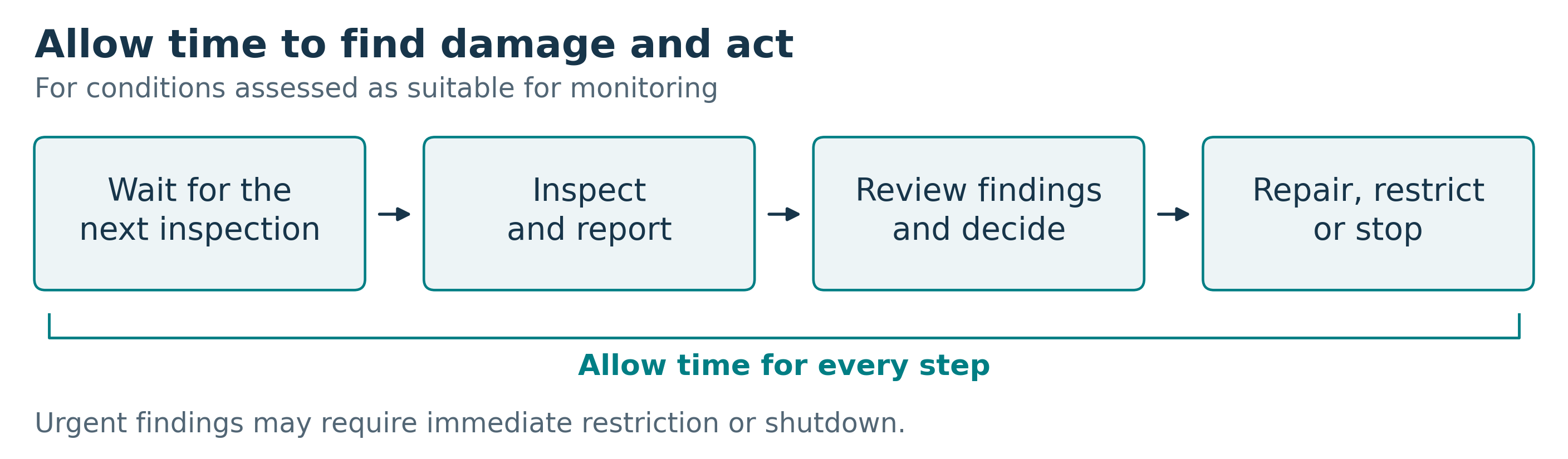
Before monitoring starts, name the person who will review the findings and the person authorised to restrict or stop the machine.
State how long continued operation is justified, using a date or a defined amount of operation, such as operating hours or cycles. State what must happen if that limit is reached before the next review or repair. An overdue review does not extend the approved operating period.
Also set clear responses for a missed inspection, an area that cannot be examined, changed operating duty or damage beyond the agreed limit. These events require review of the operating decision.
Act on known findings and feed them into shutdown planning
A defect that has been found but remains unresolved can still lead to an unplanned shutdown. Give each significant finding an accountable owner, a decision deadline and an interim operating basis. Carry open findings into the shutdown plan with access, isolation, temporary support, repair resources and verification requirements. The NSW coal handling review identified gaps in assigning and verifying structural remedial work. [3]
Urgent repairs can bring production losses, rushed access arrangements and uncertainty in repair quantities. Establish the extent early enough to scope the work. If the shutdown is deferred, reassess the operating and monitoring basis rather than simply moving the work order date.
Use the repair to reduce future exposure
Where repair is required, address the established cause as well as the damaged steel. Review material traps, wet deposits, drainage, corrosion protection and access for cleaning and inspection. Designed hatches or removable panels can make future examinations practicable. Assess alternative load paths in critical areas where justified, including their capacity under the damaged condition.
Check the actual support conditions before cutting or removing steel. In WA’s 2016 thickener fatality report, a corroded bridge had become dependent on a rake shaft that was then cut. [5] Deterioration can leave the structure supported differently from the drawing. Include temporary support and a hold point when dismantling reveals the full extent.
Specify fabrication quality for fatigue performance
For new structures, replacement members and repair welds, define fabrication requirements from the fatigue assessment, intended duty and service period. Identify critical welds on the drawings. Specify fit up, alignment, weld size, required penetration, toe profile and transition angle, using qualified welding procedures. These controls reduce severe local stress concentrations and imperfections that can initiate fatigue cracks. [4]
Specify the examination methods, extent and acceptance criteria for each critical weld. This may include 100% ultrasonic and magnetic particle examination where both are suitable and justified. Ultrasonic testing targets internal flaws; magnetic particle testing detects surface and near surface flaws in ferromagnetic steel. Coverage must suit the joint geometry and access. [7] A 100% examination scope does not mean every flaw will be detected or establish the fatigue life.
Where fatigue is expected at the weld toe, controlled toe grinding can remove small toe imperfections and smooth the transition into the plate. Specify treatment locations, the finished profile and material removal limits, then verify the result. Grinding may expose deeper imperfections that need assessment and correction. A smooth appearance alone is insufficient. [8]
Assess ultrasonic peening for suitable existing details
Ultrasonic impact treatment, often called ultrasonic peening, is one form of high frequency mechanical impact (HFMI) treatment. It can improve the toe profile and introduce compressive residual stress, improving fatigue resistance at suitable weld toes. It can be useful on existing structures where changing the detail is difficult. The claimed benefit must suit the material, geometry and loading, including mean stress and significant load peaks. [9]
Treatment does not restore corroded section or resolve a fatigue critical weld root. Do not peen over a detected crack as a routine repair: characterise it and establish an engineered repair or rehabilitation procedure. Use trained operators, documented treatment and acceptance requirements, and verify the result. Restore corrosion protection and retain follow up inspection. [9]
Close the action and update the next inspection
Link the original finding to the accepted repair, installed configuration, examination records and resolved deviations. Feed the damage actually found during the shutdown, any changed detail and the final measurements back into the assessment, defect register and inspection plan. Establish a post repair baseline, the next examination and its owner before handover.
Corrosion can erode the basis for continued operation while the planned shutdown date remains unchanged. The response is to reassess the damage, close inspection gaps and complete the required action within a justified period. Fabrication controls and suitable weld treatments can improve the starting condition; risk based inspection must then account for the condition found in service. The shiploader’s repaired connections and inaccessible support columns show why prevention, inspection and action must remain connected.
ACE can review inspection findings and develop investigation, repair and monitoring scopes. The starting information is the defect register, original examination reports, repair history and the operating or shutdown decision that needs to be made.
References
[1] Department of Mines, Industry Regulation and Safety, WA (2019). Structural failure of fixed conveyor stacker. Significant Incident Report 274, pp. 1–2. Source
[2] Department of Mines and Petroleum, WA (2015). Structural safety of buildings, plant and other structures. Mines Safety Bulletin 124. Source
[3] NSW Resources Regulator (2017). Structural integrity of coal handling and preparation plants, pp. 4–5 and 22. Source
[4] Hobbacher, A. (2008). IIW Recommendations for Fatigue Design of Welded Joints and Components, IIW-1823-07, sections 3.5.3, 3.5.5, 3.6, 5.4–5.5; corrections 17 October 2012. Source
[5] Department of Mines and Petroleum, WA (2016). Failed gantry bridge crushes boilermaker working in thickener tank: fatal accident. Significant Incident Report 244. Source
[6] Zhang, Y., TWI. Fatigue Crack Growth Testing. Source
[7] Australian Institute for Non-Destructive Testing. What is NDT? Source
[8] Zhang, Y.-H. and Maddox, S. J. (2009). Fatigue life prediction for toe ground welded joints. International Journal of Fatigue 31, 1124–1136. Source
[9] Marquis, G. B., Barsoum, Z. and Leitner, M. (2025). New developments and guideline updates for HFMI treatment for improving the fatigue strength of welded joints. Welding in the World, sections 2–3 and 5. Source