
Establish the current operating decision
Before planning the repair date, establish whether continued operation has an adequate engineering basis. The crack extent, affected load path, potential growth and failure consequences may require further examination, operating restrictions or removal from service before the planned shutdown.
The IIW recommendations link the investigation to the choice between immediate repair, delayed repair, monitoring and changes to operation. Where service with a known crack is proposed, assess that crack and its potential growth under the proposed duty. A fatigue design check for an assumed uncracked detail is not, by itself, a basis for operating with a detected crack. [1]
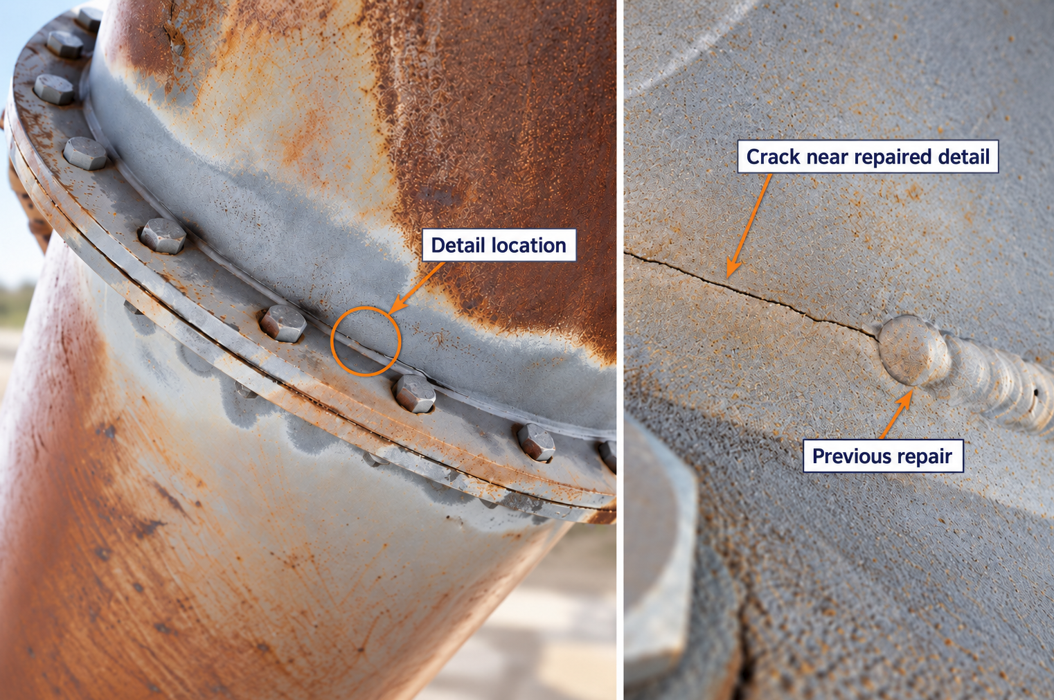
Start with what happened to the previous repair
A crack appears beside a plate added during the last shutdown. The repaired weld is still intact, so the new finding is entered as another defect. That may be administratively convenient, but it separates two observations that could belong to the same structural problem.
For a stacker, reclaimer or shiploader, recover the sequence before deciding what to weld. Record the original crack location, its extent, the repair drawing, what was installed and the duty since the work. Include nearby repairs and changes to supports. A photograph of the latest crack rarely answers those questions.
The investigation should establish whether the previous intervention failed to achieve its intended detail, whether that detail was unsuitable for the actual loading, or whether another mechanism is involved. Those possibilities lead to different work packages.
Where fatigue has not been established, check whether the crack features, discovery timing and service history support another mechanism, such as fabrication cracking or overload.
Separate repair intent from the installed detail
Consider an illustrative repair in which the drawing requires a particular groove preparation and weld penetration to transfer cyclic load. The shutdown record says the weld was completed, but contains no preparation photographs, inspection coverage or record of a site departure. Renewed cracking alone cannot establish whether the design or its execution was responsible.
The assessed fatigue detail must match what is present. A weld symbol on a drawing establishes an instruction. It does not establish penetration in the installed joint. Equally, missing records are an evidence gap; they do not prove poor workmanship. Decide what examination can resolve the uncertainty before crediting the repair with its calculated resistance.
The following comparison is a practical starting point for the repair review. Each line should identify the evidence available and the specific gap that remains.
Intended repair
- What to establish
- The crack mechanism, required detail and service objective
- Evidence that helps
- Assessment, controlled drawing and repair procedure
Installed repair
- What to establish
- The geometry, weld preparation, material and departures actually present
- Evidence that helps
- Site records, measurements and examination suited to the joint
Verified condition
- What to establish
- What was examined and which flaws or dimensions the method could assess
- Evidence that helps
- Inspection location, method, coverage, acceptance basis and results
Service response
- What to establish
- Where cracking or movement occurred after the intervention
- Evidence that helps
- Comparable inspection records, duty history and targeted measurements
Keep local causes in the investigation
Incomplete crack removal, a significant repair imperfection or an unfavourable weld profile can explain recurrence without a complex whole machine model. Establish crack extent and plausible origin, including whether it starts at a weld toe, root or adjacent plate. Select the inspection method for the suspected flaw and the available access.
A treatment intended to improve fatigue resistance at the weld toe needs a suitable repaired detail. The weld root and other possible crack origins still require assessment. [1]
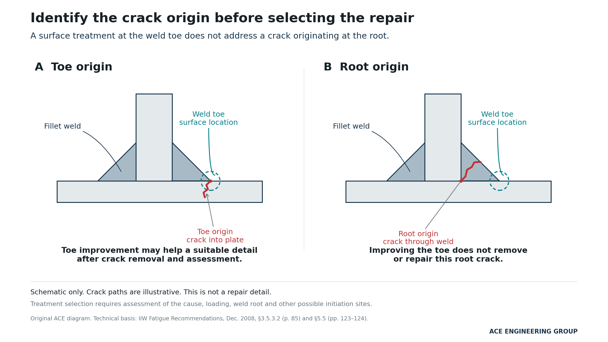
There is no universal fraction of original fatigue life that can be assigned to every repair. The result depends on crack removal, the installed detail, repair quality and subsequent loading. Dexter and Ocel distinguish repairing an existing welded detail from introducing a weld into previously unwelded material, where the repair itself changes the fatigue detail. [2]
Published tests illustrate why this matters. Repairs to simple attachment details in SSC 425 had lower fatigue resistance than the original specimens. The authors identified changes in the detail, weld quality and restricted access as influences on the results. Kudryavtsev and colleagues, however, reported substantial restoration of initial fatigue life for the repeatedly repaired welded specimens they tested. Neither study establishes the life of a repaired bulk handling machine. Both support assessing the actual repair rather than applying a standard life penalty. [3], [4]
Australian mining experience also shows why closing a weld repair does not necessarily close the structural issue. WA Mines Safety Bulletin 124 describes ineffective weld repairs and patching to cracked support steelwork beneath a ROM bin, with the remaining members cracked through and displacing. The bulletin identifies failure to remedy root causes during successive repairs as a contributory factor. It does not establish a fatigue mechanism for every incident described. [6]
Loading still needs attention. Material loading, conveyor starts, luffing, slewing and vibration can repeatedly stress the same region. An unchanged operating setpoint does not establish unchanged local stress if supports, connection stiffness or material accumulation have changed. The article on operating duty and fatigue explains how to investigate changed response and duty without treating visible movement or an alarm as proof of damaging stress.
Check where the movement goes
In a second illustrative situation, a reinforcement plate reduces flexing at the cracked connection. The plate is correctly installed and its weld passes inspection. Relative movement between the connected members remains, however, and becomes concentrated at the plate termination or the next connection. The repair has changed where part of the cyclic deformation occurs.
Assess how load enters and leaves the modified region, including eccentricity, support flexibility and restraint. Compare all credible crack locations. A substantial reduction at the original hotspot can leave another corner governing. A model cut off at the repair boundary may conceal this behaviour.
For hollow section joints, local wall flexibility and secondary bending can be significant. CIDECT Guide 8 also highlights the location of reinforcement plate ends because the added detail can introduce adverse notch effects. Check the original crack location, new attachment welds and plate ends using a consistent fatigue assessment method. [5]
Adding stiffness can be effective. In other situations, allowing a particular movement may reduce distortion. Any release needs checks of the functions that the connection still has to provide, including stability and retention. Cutting a slot or hole also changes net section and creates new edges that need assessment. [2] The article on adding steel and load paths develops the checks on original design intent and the receiving structure.
Give the repair a defined service objective
The owner should state the intended operating period and duty before the repair is selected. A repair supporting an assessed transition to replacement has a different objective from a modification intended for extended service. Both require a technical basis and workable inspection arrangements. Where the replacement date has moved, the article on repair and replacement planning explains which parts of the service decision need to be reopened.
Distinguish retained material from new parts. Reducing future stress does not remove an existing crack or erase previous fatigue exposure in untreated material. The assessment should explain which detail changes, what benefit is predicted and which parts remain dependent on their earlier condition and loading history. [2]
Design the shutdown sequence
Identify the forces carried by the affected member before material is removed. Temporary supports, isolation and the cutting and welding sequence may govern whether the proposed repair can be executed. Access and weld position can also determine whether the specified joint is achievable on site.
The procedure should address the structural and metallurgical effects of further welding, confirm crack removal and define examination of the completed joint. [1], [2] Specify any weld improvement treatment for a stated purpose and applicable detail. Treatment of a weld toe does not, by itself, resolve an unassessed root flaw or an unsuitable load path. [1]
Where crack extent or remaining thickness can only be established during the shutdown, set a hold point and an engineering response. The crew needs to know who decides if excavation extends beyond the assessed region and what support must remain in place while that decision is made.
Close the issue at the right level
An accepted inspection report confirms the result of a defined examination. It does not independently verify the operating loads or demonstrate the predicted service life. Retain the final repair configuration, inspection coverage and unresolved assumptions with the defect history.
Where later inspection or measurement is part of the service basis, specify locations, timing, access and action triggers. Record the repair and adjacent terminations together so that a crack moving to a nearby detail remains visible in the history. If the mechanism remains uncertain, identify the working explanation and the evidence needed to test it.
ACE can review a recurring crack and its repair history to identify the evidence needed for the operating decision, assessment and repair scope.
References
[1] Hobbacher, A. (2008). Recommendations for Fatigue Design of Welded Joints and Components. IIW-1823-07, December. Sections 3.5.3.2, pp. 85 to 86, and 5.5, pp. 123 to 124.
[2] Dexter, R. J. and Ocel, J. M. (2013). Manual for Repair and Retrofit of Fatigue Cracks in Steel Bridges. FHWA-IF-13-020, March, pp. 31 to 33, 42 to 45, 60 and 75. Read source
[3] Dexter, R. J., FitzPatrick, R. J. and St. Peter, D. L. (2003). Fatigue Strength and Adequacy of Weld Repairs. Ship Structure Committee, SSC 425. Section 3.1, pp. 27 to 33.
[4] Kudryavtsev, Y., Kleiman, J. and Knysh, V. (2008). Fatigue Strength of Structural Elements with Cracks Repaired by Welding. IIW Document XIII-2236-08, figures 8 to 10, pp. 5 to 6.
[5] Zhao, X. L. and colleagues (2000; 2001 printing). Design Guide for Circular and Rectangular Hollow Section Welded Joints under Fatigue Loading. CIDECT Design Guide 8. Sections 3.1 to 3.5, pp. 26 to 28, and 6.2.3, p. 54.
[6] Department of Mines and Petroleum, Western Australia (2015). Structural safety of buildings, plant and other structures. Mines Safety Bulletin 124, 16 September, pp. 2 to 3. Read source