Establish what needs to improve
Is a member overloaded, a bearing moving out of alignment, or a weld cracking under repeated loading? Identify the operating, fault and maintenance conditions that matter. A lower calculated stress is useful only if it addresses the original problem.
A chute support may fit the available space but apply its load between the main supporting members. A thicker plate could carry that load across the gap. Moving the support closer to a suitable member may reduce the bending instead. The choice depends on chute position, material flow, clearances and the connections available.
Find the function before removing the detail
Compare the drawings, calculations and modification history with the machine. Confirm dimensions, remaining thickness, connections and crack condition. An old drawing cannot establish the condition of an inaccessible weld or internal plate.
A plate that appears unnecessary may restrain a compression member against buckling, spread a concentrated force or support the structure during maintenance. Check its function in the completed arrangement and during removal.
For example, a model may show acceptable strength and buckling resistance with a damaged stiffener omitted. That result still depends on the plates and internal diaphragms left in place having the assumed thickness and connections. If those details are unverified, the calculation has not established that physical removal is acceptable.
Where the original purpose cannot be recovered, identify the functions the machine still requires and assess them directly. Record the basis for retaining, altering or removing the detail.
Check movement and local force transfer together
A support can have adequate strength while moving too much for its pulley, gearbox or bearing. Obtain the limits on relative displacement and rotation between mounting points, then assess the supporting assembly under the relevant loads.
Consider two shuttle rails, one above the other. A plate connecting them can limit how much they move relative to each other. It does this by transferring force from one rail to the other through its connections. These forces can cause local bending in each rail where the plate attaches.
Check whether the relative movement stays within the required limit and whether the rails and connections can carry the transferred forces. A different rail section or support arrangement may be more suitable.
Follow the force into the receiving structure
A load path is the route a force takes through connected parts to the machine supports. Follow the equipment reaction through its bolts or welds, receiving plate, supporting member and end connections. Each part must transfer the force to the next.
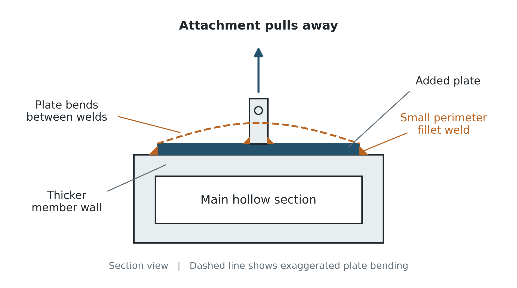
Check effective weld throat, length, loading, minimum weld size and the available plate edge geometry. The weld leg dimension differs from the effective throat used in the capacity calculation. Matching weld size to member thickness is not an adequacy check.
Under outward pull, the added plate can lift away from the hollow section and bend between its perimeter welds. Check the plate and receiving wall as well as the welds. A larger weld can help where fatigue is governed by the weld throat, but may leave plate bending or a controlling weld toe detail unresolved.
Confirm the existing steel’s grade, condition and weldability. Specify a suitable welding procedure; a weld strength calculation alone does not establish that welding is suitable.
Check force transfer through the plate thickness
In a cruciform connection, two aligned tension plates are welded to opposite faces of a central plate. Their force must cross its thickness. Restrained welding contraction can also impose through thickness strain before service. Susceptible rolled plate can tear internally; this is lamellar tearing. Check through thickness properties, service load transfer, welding restraint and inspection together. Larger welds do not resolve poor through thickness ductility, and surface inspection cannot establish internal condition.
Use the stress measure that matches the fatigue method
A nominal stress describes loading in the member without resolving every local weld effect. A local weld stress includes more of those effects. Each must be compared with the fatigue curve intended for that method. In a finite element model, a peak at an idealised sharp corner can increase as the mesh is refined. Use the stress extraction procedure required by the chosen method.
Choose how the new steel connects
A doubler plate and a collar engage differently
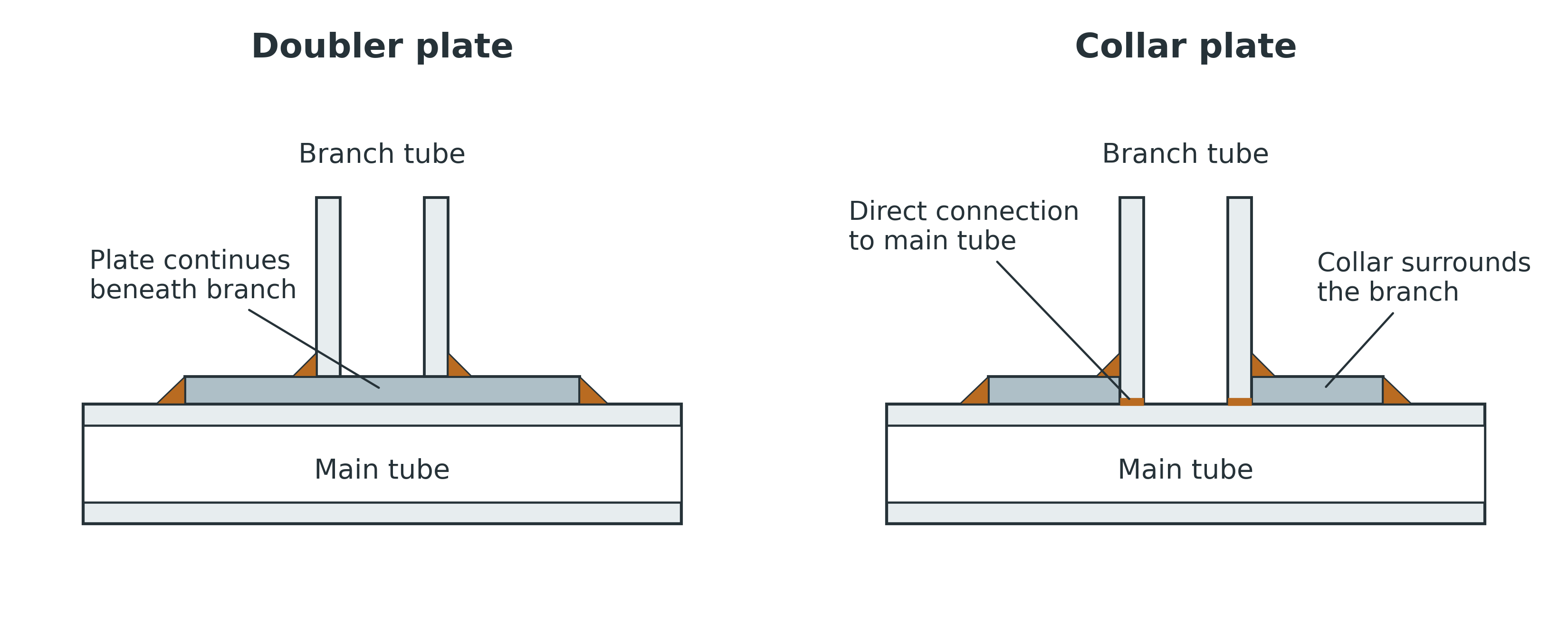
A doubler sits between the branch and the main tube. The branch is welded to the doubler, and the doubler is welded to the tube. Force from the branch must pass through the added plate.
A collar surrounds a branch already connected directly to the main tube. It is welded to both parts, so the direct connection remains alongside the collar connection. Select the arrangement for the actual load and governing failure mode; static strength does not establish fatigue life.
Put the support beneath the change in direction
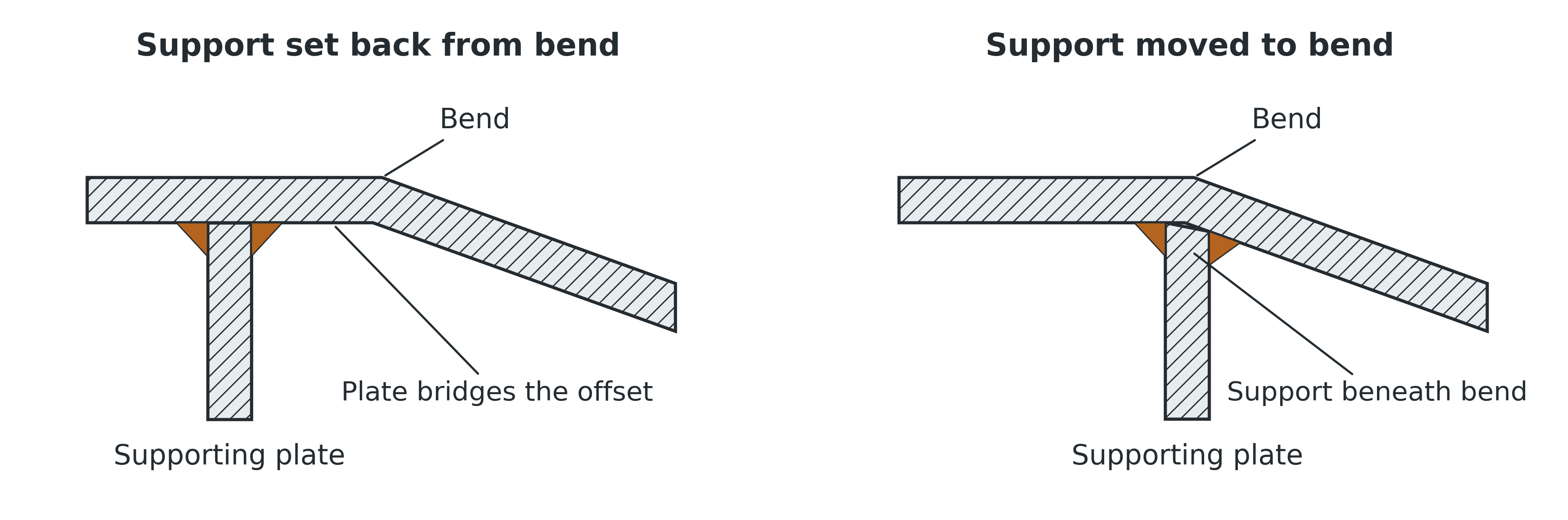
Consider a bent plate carrying axial force. Changing the force direction requires a transverse force at the bend. With the supporting plate set back, the intervening plate transfers that force by local bending. Placing the support beneath the bend gives the force a more direct route. Check the supporting plate, welds and bent plate for actual loading and local stress range.
Provide access to make and inspect the weld
A stiffener can fit the drawing while obstructing access to the joint root. The welder needs to see and reach the root, maintain the working angle and travel along the weld. Check welding and inspection access after adjacent parts are installed. Revise the detail or assembly sequence where access is inadequate.
Check the new fatigue details
Reinforcement changes local flexibility and can redistribute load. Check new welds, reinforcement ends and neighbouring details, including stress range in the receiving member. Retain the previous duty and existing condition in the assessment. Added steel does not erase fatigue damage or resolve an existing crack; define its treatment and inspection.
Detail the end of a slotted plate connection
Consider plate A fitted into a slot in plate B, at right angles to it. In the left detail, the slot closes tightly around A and the weld continues across its square end. This abrupt geometry can raise the local stress range under repeated loading.
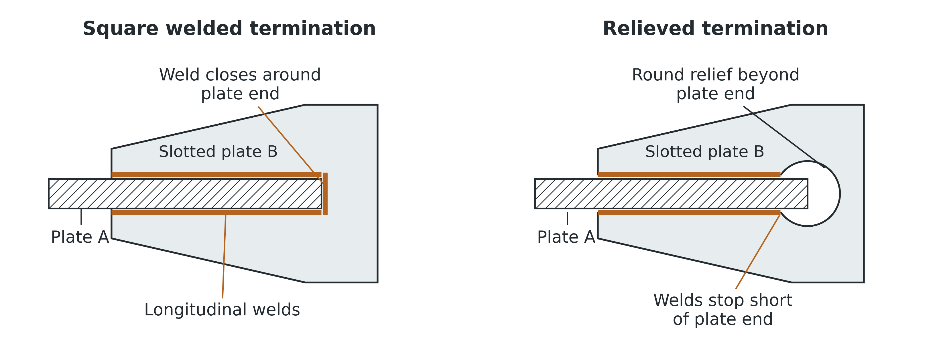
In the relieved detail, A projects into the round opening and its end remains unwelded. The longitudinal welds stop short, avoiding a weld return at the tight slot termination. The 10 mm setback belongs to this detail; it is not a general rule for every weld near a plate edge. Check effective weld length, the remaining plate section and local stresses at the relief edge and weld ends.
A small welded attachment can crack the receiving plate
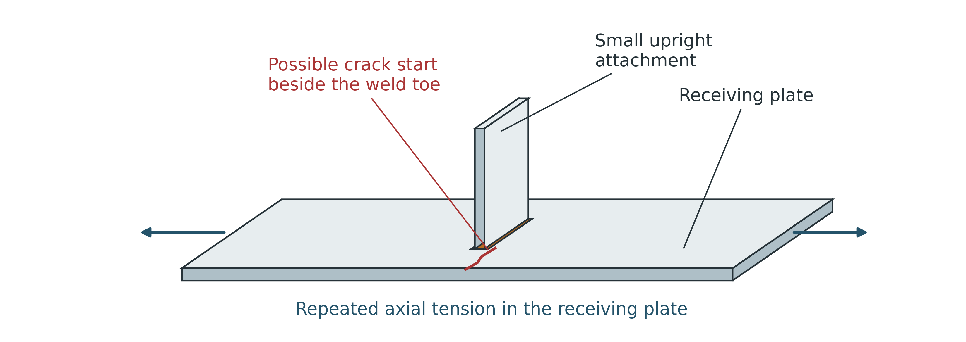
Even a small attachment can affect fatigue in the plate beneath it. When the receiving plate repeatedly stretches, the weld creates a local stress concentration. A crack can start beside the weld toe and grow into that plate. Check the receiving plate’s stress range and the fatigue detail, as well as attachment force.
At exposed plate corners, avoid undercut and weld returns across the corner. Blend undercut corrections smoothly and recheck the section.
Detail openings and changes in plate width
A round hole still interrupts a flange
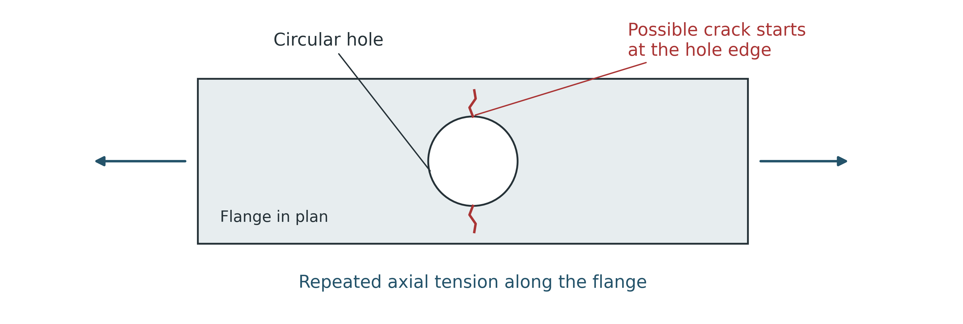
The hole forces load to pass around its edges. Local stress rises, and a fatigue crack can start there even though the opening is round. Check the remaining flange section, local stress range, nearby welds and edge condition. The shape alone does not establish adequacy.
Match the transition radius to the joint
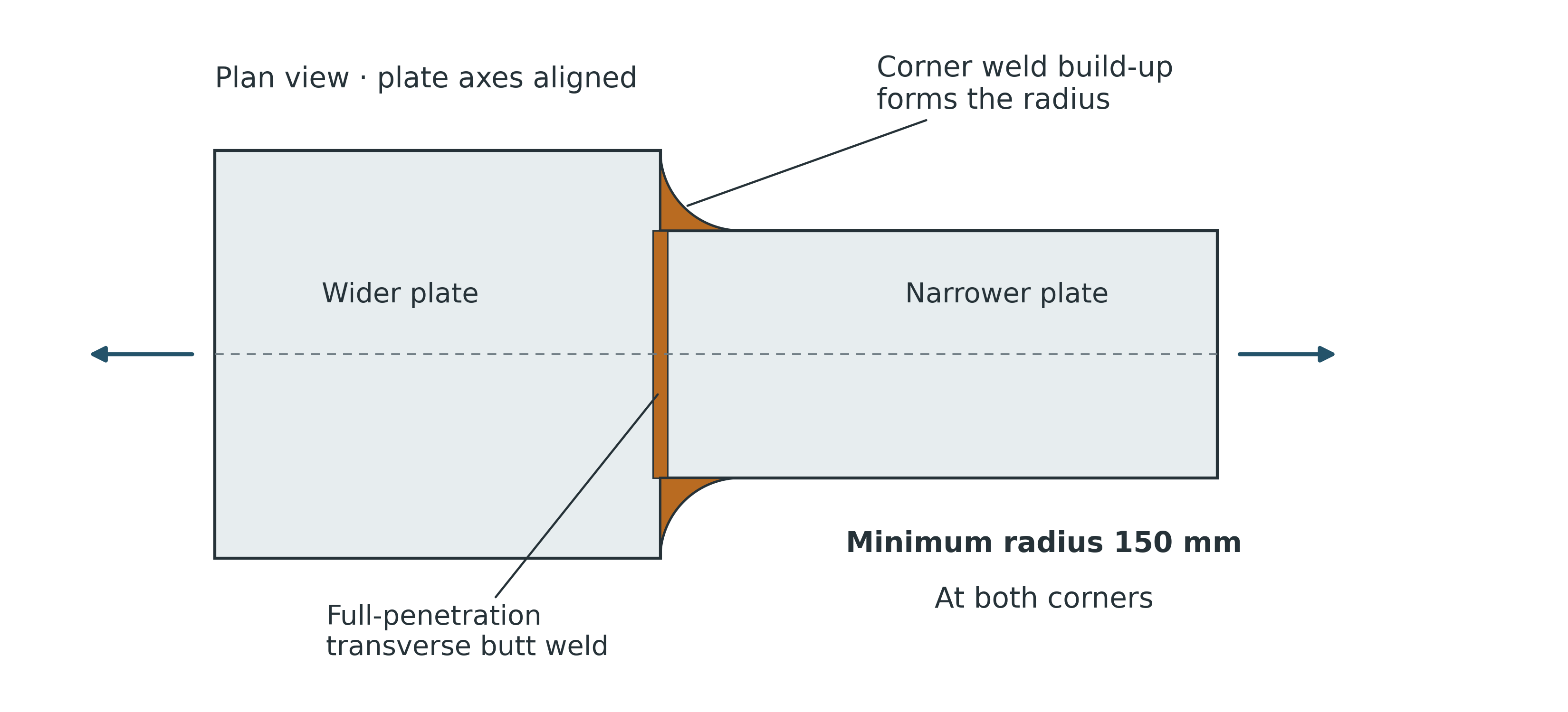
The plates lie in the same plane and have equal thickness. Their centre lines align, but their widths differ. A full penetration transverse butt weld joins them. At each shoulder, corner weld build up creates the curved outline shown.
For the illustrated detail, use a minimum radius of 150 mm at both corners. Increase the radius if required by the actual joint geometry. This is not a universal radius for slots or cut outs. Grind the corner reinforcement flush over 2t, where t is plate thickness, and meet the specified weld quality and inspection requirements.
Establish when the new steel starts carrying load
The installation sequence determines which loads the new steel can share. If reinforcement is fitted while the original member remains loaded and deformed, it does not automatically take over part of that existing load.
In this simplified axial tension example, the original member carries 100 kN and has already stretched. A second member is fitted between the same end points without forcing it into place or applying preload. It matches the deformed geometry and starts with zero force.
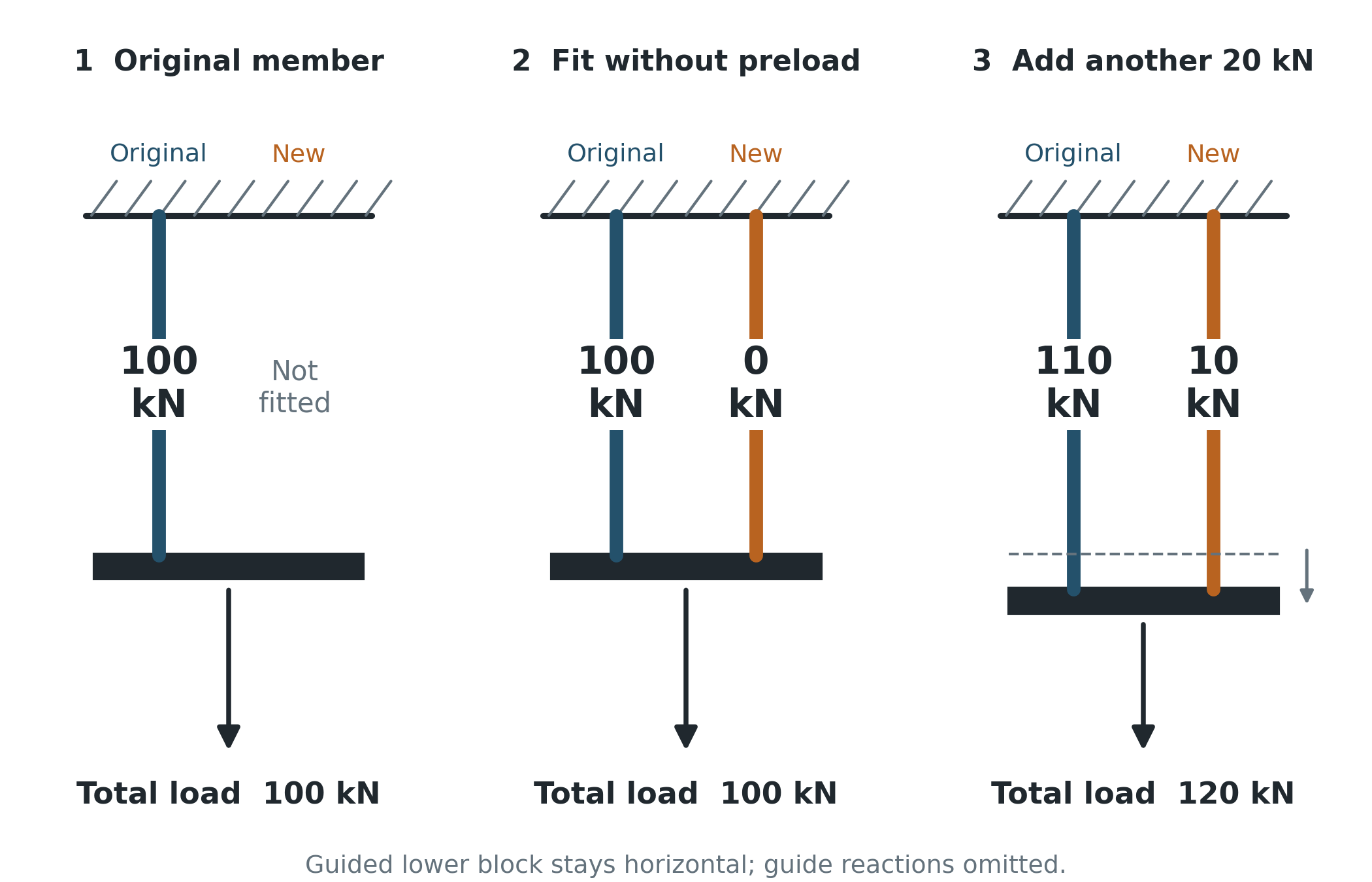
When a further 20 kN is applied, equal axial stiffness and equal additional extension give 10 kN to each member. The original member retains its initial 100 kN, so the final forces are 110 kN and 10 kN. Applying all 120 kN to an initially unstressed completed model would instead predict 60 kN in each member. That represents a different installation history.
For subsequent cycles between total loads of 100 and 120 kN, the original member cycles between 100 and 110 kN. Its force range is smaller even though its original load remains. Any fatigue benefit still depends on the weld details, previous duty and new connections.
This example assumes that completing the connection introduces no preload or movement. Welding induced heating, shrinkage and redistribution are excluded. It explains elastic load sharing, not buckling resistance or ultimate capacity.
If the design relies on relieving existing load, define engineered unloading or controlled load transfer before the reinforcement is engaged. The analysis and site sequence must represent the same stages.
Allow for welding shrinkage
Contraction from an off centre weld can bend a plate or section. Where practical, balance weld placement and sequence, and limit weld volume to what the design and procedure require. Restraint can hold alignment while increasing residual stress and cracking risk. Specify how shrinkage will be accommodated.
Carry the consequences through installation and service
Check the whole machine as well as the local member
Record added and removed mass at its actual location. Steel added near a bucketwheel changes the weight moment about the boom pivot and can affect cylinder forces, machine balance and support reactions. Assess the relevant machine positions. A changed link length also requires the mechanism geometry to be reassessed.
When checking overall slew bearing actions, consider the complete assembly above it and all other supports or connections crossing that boundary. Internal action and reaction pairs cancel when the assembly is treated as one body. A higher internal link force alone does not prove a higher overall bearing force or overturning moment. Weight, external loading and geometry determine those actions; local bearing and bolt demands can still change with support stiffness.
Load position also matters locally. A vertical force acting to one side of a beam’s shear centre can twist the beam. Loading through the shear centre avoids that source of torsion, but local flange bending and web demand still need checking.
Preserve inspection access, drainage and component removal routes. A new plate can trap material or hide a critical weld. Assess any additional use of access frames or guards as lifting points or temporary supports.
Establish the repair condition before welding
A stopped machine still carries dead load. Cutting or gouging removes load carrying material, and welding heat can temporarily reduce capacity. Check temporary support, excavation, welding and release of supports as separate stages, including stability of the supports and machine.
If an unloading target of about 20 MPa is used, the repair plan must define the stress measure, location and repair stage to which it applies. Reaching that target does not by itself establish that gouging or welding is acceptable.
Check the remaining section during excavation, specify the support and load transfer sequence, and verify the permitted repair condition before work starts. Confirm connections are complete before transferring load. Unloading reduces applied load stress; it does not remove locked in welding residual stress.
Dress the weld toe where it governs
Where fatigue is expected to start at a weld toe, controlled burr grinding removes small toe imperfections and blends the weld into the plate. It reduces local stress concentration without eliminating it. Surface polishing can leave flaws below the original toe. Preserve the required throat and plate section, and inspect the finished surface by suitable non destructive testing. Assess other crack sites, including the root. Existing fatigue cracks need assessment and a defined repair. Protect the dressed surface against corrosion; pitting can undermine the benefit.
Verify the modification against the original problem
Define the evidence needed before fabrication and the acceptance checks after installation. These may include weld inspection, alignment measurements or movement under load. Confirm that the change addresses the governing problem, engages the intended load and leaves adjacent details acceptable. Record the final configuration and the function of details that future modifications could disturb.