What the wharf inherits from the machine
At my first PIANC APAC conference in Brisbane, I was interested in how much of a wharf problem could still be resolved through the machine design. I normally approach these decisions from the machine side. The conference brought that perspective alongside the people responsible for the berth and the wider port operation.
In the Dalrymple Bay presentation, the replacement shiploader was described as more than 30 per cent heavier. My understanding of the case was that the machine and berth were developed together: corner spacing and the bogie arrangement were worked against the existing rail girders and piles. Targeted berth work was still required. The useful lesson was to test the wheel arrangement before accepting extensive strengthening as inevitable. [1]
The additional mass still had to be supported. However, changing where wheel groups land and how reactions are shared can reduce a particular girder moment or redistribute demand between supports. A lower governing effect in one member does not mean that total vertical load, every wheel load or every pile reaction has reduced.
Define how the duty is changing
Higher throughput does not automatically mean higher peak wheel loads. More operating hours may increase repeated loading without changing the maximum reaction. A heavier replacement, more material carried on the machine, a changed centre of gravity or higher operating speed can affect different parts of the loading assessment.
Establish what changes in the proposed operation: installed mass, retained material, material carried, speeds, operating hours and travel or slew movements. Then assess peak actions, their distribution and the relevant load cycles. The same production increase can require a different engineering response depending on how it is achieved.
Provide actions that belong to the same condition
Separate maxima for vertical, longitudinal and transverse forces may come from different machine positions and cases. Combining them can create an unrealistic condition; selecting them without accompanying actions can miss a governing interaction. Higher compression can improve resistance to uplift or frictional sliding, so pairing maximum horizontal force with maximum compression is not automatically conservative.
Issue signed, simultaneous actions across the complete support arrangement, including individual wheel loads and positions where relevant. State the machine configuration, coordinate system, application points and force directions. Identify characteristic or design values, the action factors and dynamic allowances already included, and the combinations still required by the receiving designer. Retain the underlying cases and action components.
Wheel spacing changes the response
Consider a simply supported rail girder of span L carrying two equal vertical wheel loads P, symmetric about midspan and spaced s apart. Ignore self weight, dynamics and other loads. Each support reaction is P. The bending moment between the wheels is P × (L − s) ÷ 2. Increasing spacing from L/4 to L/2 reduces this centred moment by one third, while total vertical load remains 2P.
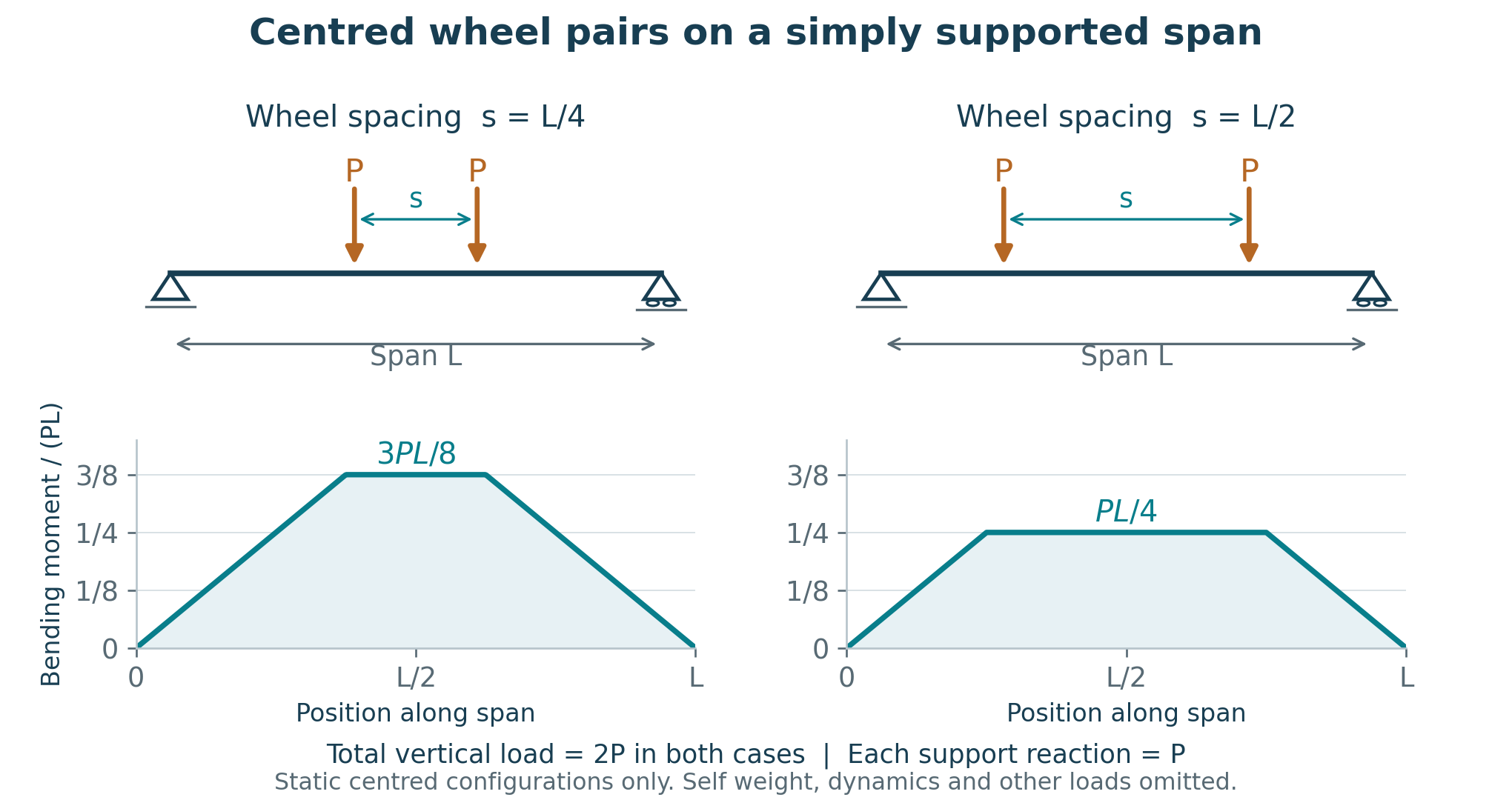
For the same idealised beam during travel, maximum bending falls from 0.3828PL to 0.2813PL, a reduction of 26.5%. If each wheel load also rises by 20% at the wider spacing, maximum moving bending remains 11.8% lower, while maximum support reaction rises 2.9% and wheel load rises 20%. These maxima occur at different travel positions. Assess the complete arrangement, including continuous spans, neighbouring wheel groups, local rail effects and foundations.
Check how the supports influence the machine
Equalisers and articulated supports share loads only within their available movement and actual condition. Check contact, clearances, seized joints, stops and credible rail displacement. Equal reactions assigned to identical wheel groups can conceal the consequences of lost articulation or contact.
Uneven support does not produce the same response in every machine. Some movement may be accommodated by articulation or whole machine inclination. Other movement can distort the frame or redistribute reactions. Trace the actual mechanism before attributing higher slew resistance, bearing edge loading or unequal cylinder forces to settlement.
The infrastructure designer should return rail displacements, rotations and differential settlement for the relevant cases. Combine these with surveyed deviations using consistent coordinates and a defined reference state, avoiding double counting deformation already present in the survey. The machine designer should check contact, articulation, inclination and any distortion transmitted to connected mechanisms. Use sensitivity checks or a combined model where the interaction affects the decision.
Separate geometry from condition and capacity
A rail survey establishes geometry at a particular time. It does not directly establish support stiffness or structural capacity. Inspection establishes condition within its coverage. Recover drawings and modifications, measure relevant section loss, and identify uncertainties in connections and foundations. Include the rail position relative to the girder web, as well as gauge, level and alignment.
Rail eccentricity can introduce repeated local flange and web bending as wheels pass. Where the connection detail is comparable, fatigue cracking may develop at the flange to web connection. [2] Investigate unexplained cracks against the actual detail, fabrication, corrosion, restraints and load history as well as support behaviour. One plausible mechanism is not a diagnosis.
For crawlers assess the track and ground together
Ground pressure varies with machine configuration, load position and track contact. Average machine weight divided by nominal track area is only a screening value. Establish the pressure distribution and assess bearing resistance, total and differential settlement, and the machine’s allowable inclination for the operating conditions.
Steel plates or mats may improve load distribution, but their presence does not establish adequate bearing or settlement performance. Check their strength, stiffness and contact together with the underlying ground, including deeper weak layers. CICA/CANZ guidance addresses these principles for cranes. [3] Machines operating on leach pads require their own geotechnical and equipment assessment basis.
Check the bearing installation against the revised duty
A slew bearing assessment needs concurrent axial force, radial force and overturning moment for the relevant cases, together with the duty spectrum. Torque about the vertical slew axis is a separate action. Restoring a balance moment does not establish that bearing forces, bolt demand or service life remain unchanged.
Manufacturer guidance distinguishes static capacity, bolt capacity and service life, and requests load spectra, slew movements, speeds and gearing demand. [4] Obtain the selected bearing’s assessment for the proposed duty. A generic catalogue curve does not establish acceptance of the complete installation.
The mounting structure is part of that installation. Local deformation can concentrate raceway loading even when the global portal stress is acceptable. [5] Check the supporting rings, connections, flatness, bolt preload and joint separation against the selected bearing requirements. For a retained bearing, reconcile its identity, condition and operating history with the intended further service. Reduced future loading does not erase previous damage.
Include recurring actions and credible faults
Normal travel includes acceleration, braking and guidance forces. Mid West Ports guidance addresses braking traction and drive distribution to minimise crabbing. [6] Recurring actions may contribute to fatigue. Assess the relevant load ranges, cycles, travel distribution and prior service; a satisfactory peak strength check does not establish remaining fatigue life.
Assess drive faults, emergency stops, parked and storm restraint conditions on their own physical basis. Trace buffer, clamp and anchor forces into the supporting structure. Where protection is credited with limiting demand, establish the forces developed during detection, control response and stopping. A trip setting alone does not establish the maximum structural load.
Use measurements to test the model
Weighing can test calculated mass, centre of gravity and reaction sharing in a defined configuration. Record machine position, retained material, equipment state and measurement uncertainty. Durst and Vogt discuss this use of weighing and the dependence on measurement method. [7] One measured condition does not validate the complete operating envelope. Combine measurements with the configuration records and assessment cases they can actually support.
Carry the assessment through every temporary stage
The Groote Eylandt cyclone recovery showed the relationship between the machine and wharf under a different condition. Aurecon’s account describes staged stabilisation and demolition around the damaged shiploader and offshore substation. Temporary supports were installed from above, with the design depending on which surviving parts of the damaged structure could carry them. [8]
The engineering lesson is that every significant removal stage can change the structural system. Supports disappear, continuity changes and temporary restraints carry actions absent from the operating model. At some stages, the temporary load path is the job. Assess the significant configurations and the transitions between them, including removal, jacking and temporary restraint.
Agree the information needed for release
| Interface information | What to record | Decision supported |
|---|---|---|
| Actions | Concurrent signed forces and moments across all supports; cases, wheel positions, components and factors | Demand on the receiving structure |
| Support behaviour | Contact, articulation and stiffness; surveyed deviations, predicted movements, reference state and limits | Whether the modelled load sharing is achievable |
| Duty and history | Load ranges, cycles, travel distribution, prior service and intended further life | Strength, serviceability and fatigue assessment |
| Existing condition | Survey, inspection coverage, measured loss and evidence gaps | Capacity credited to retained assets |
| Configuration | Drawing revision, equipment masses and temporary stages | Whether both designers assess the same machine |
| Acceptance | Criteria, responsible designers and unresolved conditions | Release of the complete arrangement |
A screening exceedance remains unresolved until justified assessment or an accepted design measure addresses it. A refined model may reduce an apparent demand, but it may also reveal a worse condition. Compare layout changes, strengthening and operating measures against the same agreed basis.
Before release, identify the governing case at each interface, the accepted capacity and movement limits, and the remaining verification. Coordinate installed mass, rail geometry, articulation and bearing mounting checks with commissioning. WA plant guidance addresses suitable foundations, stability during installation and checks against design specifications during commissioning. [9] Any credited operating restriction must also reach the controls and operating documents.
ACE can develop machine action sets and assess arrangement options with the infrastructure and bearing specialists. The outcome should show what needs changing, where the evidence supports retaining existing assets, and which unresolved condition could still change the scope.
References
[1] PIANC APAC 2026. Conference presentations index, including Synergistic Design: integrated solutions for shiploader replacement at Dalrymple Bay Terminal. Source
[2] Konecranes (2025). Rail to girder eccentricity matters, PDF pp. 3–4. Source
[3] CICA and CANZ (2017). Crane Stability and Ground Pressure, CICA-GN-0013-A, sections 3.4–3.5, 4.2 and 5.1. Source
[4] thyssenkrupp rothe erde. Technical basics: Bearing selection. Source
[5] thyssenkrupp rothe erde. Technical basics: Companion structure. Source
[6] Mid West Ports Authority. MWPA301 Bulk Handling Facility Guidelines General, section 7.5.2, printed p. 38, PDF p. 43. Source
[7] Durst W and Vogt W (1988). Bucket Wheel Excavator. Series on Mining Engineering, volume 7, Chapter 7, printed pp. 229–233; weighing discussion p. 232.
[8] Aurecon. Milner Bay Port Facility Wharf Recovery, Northern Territory, Australia. Source
[9] Work Health and Safety Commission, Western Australia (2022). Managing risks of plant in the workplace. Code of practice, section 3.2, printed pp. 29–30. Source