
Compare three complete arrangements
For a capacity upgrade, assess the drive change together with larger buckets and boom conveyor modifications. Their combined effect may increase counterweight demand even where the selected drive is lighter. Package price and package mass cannot settle the decision.
An electromechanical arrangement places the electric motor and gearbox near the bucketwheel. Include a suitable compact planetary gearbox in the comparison, with its motor, mounting and accessories. Obtain the mass, dimensions and support loads of the complete proposed package.
In the hydraulic direct drive arrangement considered here, a hydraulic motor drives the bucketwheel shaft while a separate hydraulic power unit, or HPU, contains the electric motor, pumps and associated equipment. Compare an HPU on the slew deck with one on the counterweight boom. For each option, prepare a layout, complete operating mass schedule, support loads, service routes and removal method. These define the installation being priced.
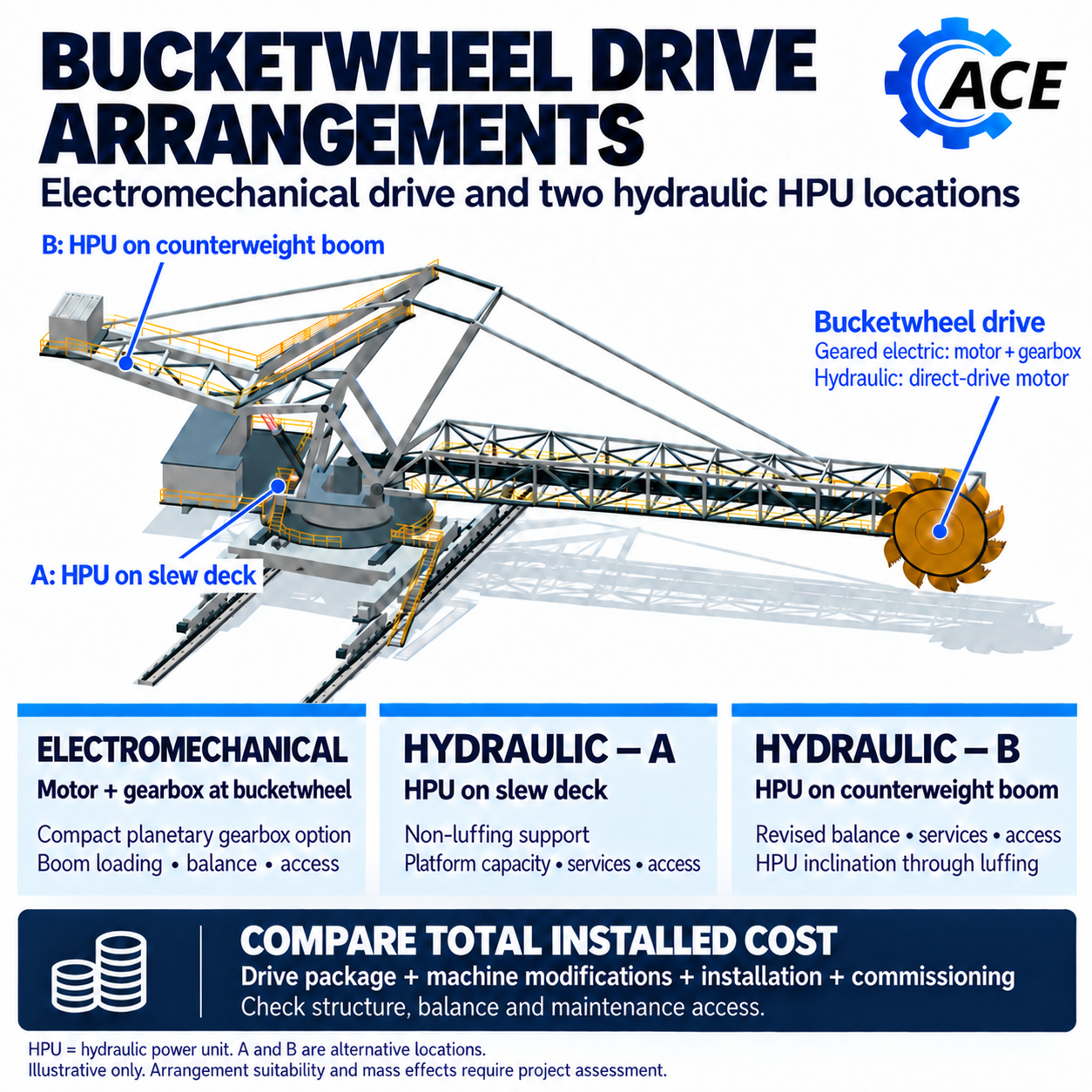
HPU on the slew deck
On a slew deck that does not luff, the HPU loads the deck and its supporting structure. It changes the overall mass distribution and support reactions, but provides no direct gravitational counterbalance to the moving luffing assembly. Any ballast reduction associated with the lighter bucketwheel equipment must be calculated separately.
A central location may offer a shorter hydraulic route than the rear counterweight boom. Confirm the route, including movement loops, supports and protection. Reserve the space needed for luff cylinder removal, conveyor drive replacement and chute maintenance, as well as access to the HPU.
An HPU can fit during operation and still obstruct a later change out. Distinguish routine servicing space from the larger clearance needed to remove an electric motor, pump or nearby machine component. Check the removal envelope and lifting route as well as the equipment footprint.
HPU on the counterweight boom
On a counterweight boom that moves with the luffing mechanism, the HPU can contribute to the counterbalancing moment. Combined with mass removed at the bucketwheel, it may permit further removal of existing ballast. The credit depends on operating mass, position and the actual linkage through the luffing range. It is not automatically equal to the HPU mass.
That benefit may require additional supporting steel, platforms and lifting access. The hydraulic route may also be longer. Compare line size, flow, pressure loss and control response for the proposed arrangement. Check return and case drain pressure against the selected equipment limits, and allow for hose movement and the effect of fluid compression on drive response.
Confirm the selected HPU’s permitted inclination through the full luffing range, including reservoir oil levels and suction, return and drain arrangements. A suitable mounting or levelling arrangement may be needed if the equipment cannot accommodate the movement. Any levelling system adds mass, cost and maintenance. A permissible angle for another power unit is not evidence that this one is suitable.
Establish how the HPU will be serviced and removed. Removing equipment that contributes to counterbalance changes the maintenance configuration and may require temporary support or ballast. Include that work when judging the location.
Calculate the complete mass change
Include all removed and added equipment at its actual position: bucketwheel motor, HPU operating mass, pipework and oil, supports, guards, platforms and counterweight changes. Confirm whether quoted weights cover the complete assembly and operating fluids. Account for any excluded components before using those weights in the balance assessment.
Check luffing balance, whole machine stability and the affected member, linkage, bearing and support reactions across the relevant positions and load conditions. Restoring luff cylinder force at one position does not establish that the original loads have been restored elsewhere. The article on machine balance explains the measurements and linkage assessment needed to interpret that result.
Keep the differences visible
Use the actual layouts to develop the scope. The table identifies the main location consequences; it does not rank the arrangements.
| Comparison | Electromechanical | Hydraulic with slew deck HPU | Hydraulic with counterweight boom HPU |
|---|---|---|---|
| Luffing balance | Motor and gearbox mass near the bucketwheel | Bucketwheel drive mass changes; deck HPU gives no direct luffing counterbalance | Bucketwheel drive mass changes and HPU may replace some ballast |
| Local structure | Drive mounts and bucketwheel boom | Bucketwheel motor mounts plus deck supports | Bucketwheel motor mounts plus counterweight boom supports |
| Services | Electrical supply and selected lubrication or cooling | Hydraulic and electrical services; route depends on layout | Hydraulic and electrical services; route depends on layout |
| Maintenance | Drive removal and temporary balance | Preserve deck change out routes and HPU removal space | Provide access and lifting reach; check balance during HPU removal |
Require the same duty and acceptance basis
Compare bucketwheel shaft torque and speed over the operating cycle, including peak duration, loaded starts, reversals and credible overloads. Equal installed kilowatts do not establish equivalent duty. Confirm the production constraint before increasing drive size: bucket filling, discharge, transfer capacity and manoeuvring can limit useful output. The reclaiming study distinguishes theoretical output from effective capacity and treats availability separately. [1]
A lighter drive still transmits torque reactions into its mounting and the machine. Agree the normal, peak and protective event loads with the drive supplier and assess the resulting structural actions. A pressure or current setting alone does not demonstrate a limit on every action. Assess retained condition and fatigue exposure under the proposed duty, and confirm the selected equipment’s thermal capability at the intended duty and site conditions.
Schmidt and van Rensburg’s portal scraper reclaimer case illustrates the integration risk. It involved larger motors supplied without designer consultation, incorrect torque protection, overfilled fluid couplings and ineffective stockpile protection. The lesson is to keep procurement and commissioned protection tied to the structural load basis. The case does not favour either drive technology. [2]
Before procurement, agree who accepts the mechanical duty, structural loads, hydraulic or electrical protection, and commissioned performance. Record the evidence required at each interface, including any condition that prevents acceptance. The article on design review before procurement develops this release and verification process.
Compare installed cost on the same scope
For each arrangement, include the package, engineering, structural modifications, counterweight work, electrical and hydraulic services, cooling, access structures, lifting, temporary works, installation and commissioning. Reconcile supplier exclusions against owner and contractor scope before comparing prices.
Assess each stage of equipment removal and installation, including temporary balance, supports and restraint. WA Mines Safety Bulletin 128 recommends current balance data for alterations and a balance check before work affecting stability. Its stacker incidents also demonstrate why a hydraulic lock is not positive isolation. [3] Apply the relevant principles to the actual machine and removal sequence; do not assume that the completed operating configuration represents the shutdown condition.
For hydraulics, allow for pipe installation, flushing, cleanliness verification and reinstatement. Agree the required cleanliness and acceptance method before estimating the shutdown duration. Plan what can be prepared before shutdown and allow for testing of the installed circuit.
Use identified allowances and stated assumptions where costs can be estimated. Mark unquantified scope explicitly. If an unresolved support, access or shutdown requirement could reverse the ranking, the lower estimate is not yet a demonstrated saving.
Show shutdown and maintenance costs separately
Report the cost to install and commission each option separately from shutdown production loss and subsequent maintenance costs. State any monetised production loss once and make the assumptions clear. Keep the cost boundaries consistent when comparing arrangements.
Include maintenance labour, fluid care, replacement methods, spares and available site skills. Do not assume that either technology has lower maintenance cost or better availability without comparable evidence.
Compare the strengthening avoided with the work added
Credit avoided strengthening only where the comparison identifies the members or connections that would need work under one option and demonstrates that the work is unnecessary under the other. A higher priced hydraulic package can then have a lower installed cost if that avoided work exceeds its package premium and added supports, services, access and ballast work. The article on lighter machine design develops the wider assessment of mass reduction.
Where the existing boom and balance accommodate a compact electromechanical upgrade, retaining that arrangement may require fewer modifications and cost less to install. This is an installation cost comparison; it does not establish the lowest cost over the machine’s remaining life.
Recommend an arrangement only when the common duty, acceptable machine configurations and installation scope are sufficiently defined. Show the cost difference, its principal drivers and the unresolved assumptions that could reverse the result. Assign responsibility for closing those items. Weight saved is an input to the decision; the outcome is an acceptable installation with a defensible total installed cost.
ACE can assess the structural, balance and maintenance consequences of shortlisted bucketwheel drives and define a comparable installation scope for procurement.
Sources
[1] Komljenovic D, Paraszczak J, Fytas K and Drebenstedt C (2004). Methodology to Calculate the Effective Reclaiming Capacity of Rail Mounted Boom Type Bucket Wheel Reclaimer and Stacker Reclaimer. Printed pp. 3 and 9 to 10.
[2] Schmidt MJ and van Rensburg BWJ (2015). Avoiding structural failures on mobile bulk materials handling equipment. Journal of the Southern African Institute of Mining and Metallurgy 115, 179 to 184; portal reclaimer case at pp. 180 to 181. Read source
[3] Department of Mines and Petroleum, Western Australia (2015). Mines Safety Bulletin 128: Isolation issues with rail-mounted stackers. 25 November, pp. 2 to 3. Available through WorkSafe WA. Read source