Resolve the decisions that constrain later work
Transport and assembly are design inputs. Workshop module sizes depend on what can be shipped, while site assembly arrangements depend on lifting capability. [1, PDF p. 251] Transport and installation can also load parts of the structure differently from normal operation. [2, PDF pp. 2 to 3] An assessment of the completed machine does not, by itself, establish the adequacy of these temporary conditions.
The support system and tipping axis geometry also need attention during preliminary design. [3, PDF p. 5] Identify the decisions that control overall behaviour before releasing dependent details. At plant layout level, the need to coordinate overall and detailed plans is established in the materials handling literature. Applying that principle to a machine package means checking that each developing detail remains compatible with the agreed arrangement. [4, PDF p. 38]
This does not require every detail to be complete at once. It requires sufficient evidence for the particular work being committed.
Make the release decision explicit
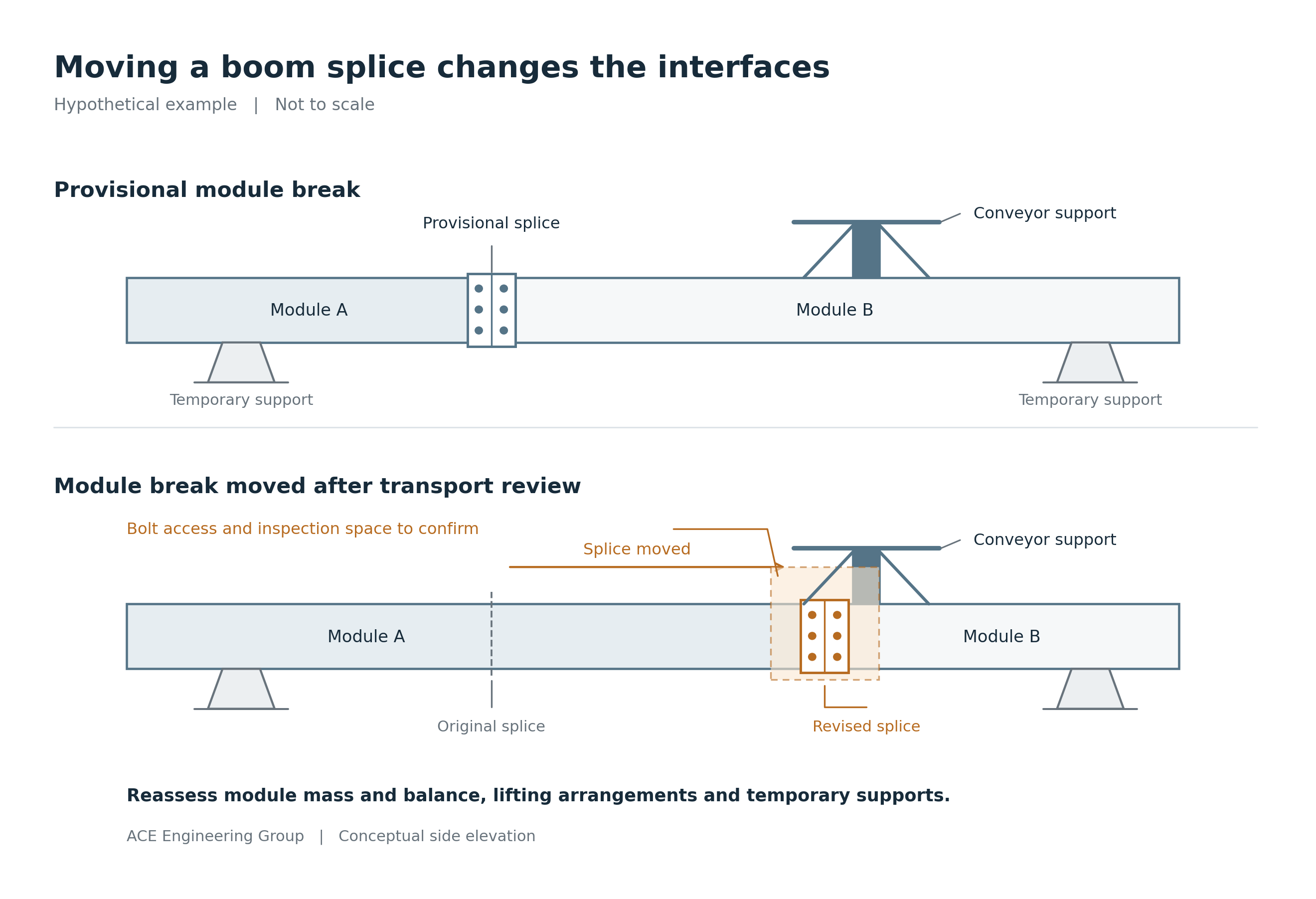
Consider a hypothetical reclaimer boom supplied in modules. The transport route, module break and assembly supports remain provisional. Moving the eventual splice could change local stiffness, module mass and centre of gravity, and could obstruct a conveyor support or bolt installation access.
The team may have enough information to compare arrangements while still lacking the basis to cut the final splice plates. A useful workshop records those different decisions explicitly.
| Work | Decision and evidence |
|---|---|
| Compare boom arrangements | May proceed within a documented range of mass, geometry and support assumptions that is adequate for the comparison. |
| Cut and drill final splice plates | Hold until the module break, connection design and interfaces are resolved for release, including transport constraints, relevant temporary conditions and assembly access. |
| Transfer the module from crane to supports | Proceed only under the accepted assembly arrangement, with the required supports, restraints and connections verified for that transfer. |
For each decision, identify who provides the missing input, who checks the assessment and who authorises release under the project arrangements. Record the restrictions and the input changes that would require the decision to be reopened. The table illustrates the reasoning; it is not an assembly procedure.
A provisional input needs defensible bounds. Calling an assumed mass conservative is insufficient: higher mass may increase lifting demand, while lower mass or a different distribution may reduce stability. Assess the relevant range and combinations for the decision being made, including centre of gravity variation where it matters.
Agree what each interface must do
Equipment reactions are only part of a mechanical interface. A pulley support also needs compatible requirements for alignment, stiffness, relative movement and attachment geometry. Poor foundations or conveyor supports can contribute to belt misalignment, and deformation at mechanical mountings can damage bearings or other components. [5, PDF p. 51; 1, PDF p. 255]
Strength alone does not establish a suitable bearing mounting. For example, slew bearing guidance addresses support rigidity, mounting surface flatness and measurement before installation. Use the requirements applicable to the selected equipment and its support arrangement. [12]
Record the controlling input and revision, its responsible party and the evidence needed to accept it. If a fabrication query proposes moving a support, review the changed load path together with alignment, services and access. Carry the accepted arrangement into both the structural and mechanical information.
Plan removal routes and lifting provisions while the surrounding structure can still change. Early provision for access and hoists is a longstanding bucketwheel excavator design consideration. [6, PDF p. 61] The practical question is whether the component can be removed and reinstated with the assessed supports and lifting arrangement.
Plan fabrication and inspection together
Explain which features the assessment relies on. A fillet weld may require separate consideration of throat failure and fatigue cracking at the toe. [2, PDF p. 2] A diaphragm may distribute a concentrated reaction; an opening may provide the access needed to weld or examine it. Those functions need to survive changes made to simplify fabrication.
The fabrication sequence should preserve the access needed to produce and accept the detail. Closing a box section or fitting an adjacent bracket may prevent welding, examination or repair. Establish the inspection stages and release conditions before that access disappears. Historical guidance supports identifying significant welds in a weld test plan. [1, PDF p. 254]
Early examination can find defects while correction is straightforward, but it may not establish final acceptance. Hydrogen cracking can develop after welding, so the examination programme must observe any delay required by the applicable code and project specification. Retain the access needed for the required examinations and any resulting repairs until the relevant acceptance conditions are met. There is no single waiting period suitable for every joint. [10]
Weld placement, deposited volume and welding sequence influence distortion. [7] Agree the datum, tolerance, measurement stage and support or restraint condition for dimensions that control mechanical fit. A dimension measured in a fabrication jig may change when restraint is released. Check the required geometry in the specified acceptance condition; do not remove restraints needed for stability merely to obtain a measurement. [11]
Assign responsibilities for fabrication methods, temporary attachments and their removal. Methods or deviations that change the assessed behaviour need review by the responsible competent designer. A temporary lifting lug can remain relevant to fatigue after its lifting duty ends; its retention or controlled removal needs an assessed basis. [2, PDF p. 3] Define permitted attachment locations, welding and removal requirements, and the surface condition and examination needed to accept the remaining structure.
Check the transfer between temporary conditions
A support arrangement can be adequate once fully engaged yet leave the structure vulnerable during the transfer of load. Identify the assembly stages that change the load path, restraint or stability, including crane unloading, engagement of temporary supports and removal of restraints. For each relevant transition, establish what must be in place and what must be verified before proceeding.
Safe design guidance includes stability during erection and installation, together with information on assembly, lifting, mass and dimensions. [13, pp. 2 to 3, 23] Apply that thinking to the actual assembly sequence. A drawing showing the final support positions does not establish that every preceding stage is adequate.
Give reviews a purpose and verify changes
ACE recommends clear responsibilities for preparation, independent technical checking and accountable approval. Fabrication and supplier reviews add different knowledge. Define the question each review must resolve, its required inputs and its release criteria. General systems engineering guidance similarly ties reviews to entry and success criteria; it is useful process guidance, not a bulk handling machine compliance requirement. [14, section 6.7]
An analysis represents the geometry, restraints and loads assessed. Differences in the actual structure or loading can make its results unrepresentative. [2, PDF p. 2] When accepting a change, identify the affected drawings, calculations, interface information and mass records, and update them together.
Added reinforcement can change mass distribution and support reactions. A material substitution may change properties, thickness, connection behaviour or fabrication requirements. Assess the relevant consequences before accepting the change, then verify that the manufactured arrangement matches the accepted disposition.
Closing the query is not the end of that process. Closure needs evidence that the change has been incorporated into the controlled documents and, where applicable, the physical item. Configuration management guidance includes verification of change implementation. [14, section 6.5] Safe Work Australia also addresses consultation over design changes and manufacture, examination and testing against design information. [8, pp. 2 to 3] Retain unresolved discrepancies for engineering disposition.
Make the lessons and handover useful
When work is repeated, record why. Planned development, an engineering error, late equipment data and a changed client requirement call for different responses. Compare the actual sequence with the information available when the commitment was made. This helps identify avoidable repetition without treating all design iteration as waste. Any claimed reduction in hours or rework needs project evidence.
Handover should preserve the accepted configuration and the evidence needed to use it: relevant examination and dimensional records, lifting information, the mass and centre of gravity basis, assembly constraints and accepted deviations. Explain the purpose of unusual details and the limits of temporary support arrangements.
Slew bearing replacement illustrates why that information matters. Jacking pads, intervening services and temporary supports can all affect the work. [9, PDF pp. 40 to 41] Preserve the machine specific provisions and assessed limits. An arrangement illustrated for another machine does not establish an acceptable replacement procedure.
A useful workshop finishes with a clear record of the work that can proceed, the decisions still holding work and the evidence required to close them. The next person should be able to understand the basis of the release and what would invalidate it.
ACE can help review the structural and mechanical decisions behind an approaching commitment and define the evidence needed to progress. The purpose is to carry a defensible decision through to the machine that is built.
References
[1] Durst, W. and Vogt, W. (1988). Bucket Wheel Excavator. Series on Mining Engineering, Vol. 7. Trans Tech Publications. Chapter 6: workshop assembly and transport, printed p. 217 (PDF p. 251); weld test planning, printed p. 220 (PDF p. 254); mechanical component mountings, section 6.1.2, printed p. 221 (PDF p. 255).
[2] Andrews, R. M. (undated). Finite Element Analysis of Welded Structures. The Welding Institute, Cambridge. “General Remarks and Pitfalls”, item 7, PDF p. 2; “Deviations from the Intended Design” and “Loadings”, PDF pp. 2 to 3; “Temporary Attachments”, PDF p. 3. Three unnumbered pages. The paper discusses historical editions of BS 7608 and PD 6493.
[3] Moczko, P., Pietrusiak, D. and Rusiński, E. (2018). “Material Handling and Mining Equipment: International Standards Recommendations for Design and Testing”. FME Transactions, 46(3), 291 to 298. DOI: 10.5937/fmet1803291M. section 2.4 “Stability”, printed p. 295 (PDF p. 5). The comparison references AS 4324.1:1995; it does not establish the requirements of the 2025 edition.
[4] Muther, R. (1985). “Plant Layout and Materials Handling”, Chapter 2, in Kulwiec, R. A. (ed.), Materials Handling Handbook, 2nd ed. John Wiley & Sons. section 2.1.5 “Phases of Planning”, printed p. 23 (PDF p. 38). The source concerns plant layout; its application to machine package coordination is an engineering inference.
[5] Fruchtbaum, J. (1988). Bulk Materials Handling Handbook. Van Nostrand Reinhold. section 2.12 “Training of Belt on Conveyor”, printed p. 29 (PDF p. 51). Supports the relationship between foundations or conveyor supports and belt alignment; it does not specify tolerances for the article’s example.
[6] Rasper, L. (1975). The Bucket Wheel Excavator: Development, Design, Application. Series on Bulk Materials Handling, Vol. 1, No. 2. Trans Tech Publications. Chapter 3 opening (PDF p. 61): initial provision for maintenance access and lifting hoists.
[7] TWI. “Distortion: prevention by design”. Sections “Weld placement”, “Reducing the volume of weld metal” and “Use of balanced welding”. Accessed 18 October 2026.
[8] Safe Work Australia (July 2014). Guide for manufacturing safe plant. Page 2: “Using the design specifications” and “Modifying the design specifications”; page 3: “Manufacturing plant”. Guidance on consultation, competent approval of modifications and manufacture against design information.
[9] Shah, K. P. (March 2019). Construction, Working and Maintenance of Stackers and Reclaimers for Bulk Materials. Chapter 5, “Replacement of Slew Bearing”, printed/PDF pp. 40 to 41. Illustrative maintenance arrangements; machine specific verification remains necessary.
[10] TWI. “Defects: hydrogen cracks in steels: prevention and best practice”. “Detection and remedial action”: delayed cracking and observance of the relevant inspection delay. Supports the timing qualification, not a universal waiting period.
[11] TWI. “Distortion: prevention by pre setting, pre bending or use of restraint”. Sections on flexible clamps, fully welded assemblies and restraints. Supports the potential for movement when restraint is released; the stated measurement condition is an engineering application.
[12] thyssenkrupp rothe erde. “Contact areas”. Technical guidance for slew bearing mounting surfaces, including support rigidity, flatness and pre installation measurement. Manufacturer guidance is applied to the relevant product and arrangement.
[13] Safe Work Australia (July 2014). Guide for safe design of plant. Printed pp. 2 to 3: information for downstream use, including assembly, lifting, dimensions and mass; printed p. 23: erection and installation stability. General guidance, not verification of the example.
[14] NASA. Systems Engineering Handbook online reference, section 6.7 “Technical Assessment” and section 6.5 “Configuration Management”. Supports review entry and success criteria, and verification of change implementation. Used as general process guidance.