
Define the arrangement and the comparison
After a heavier bucketwheel drive upgrade, a familiar luff trend can give an incomplete picture. A counterweight adjustment may bring the static luff cylinder force back towards its previous value while the centre link still carries more load.
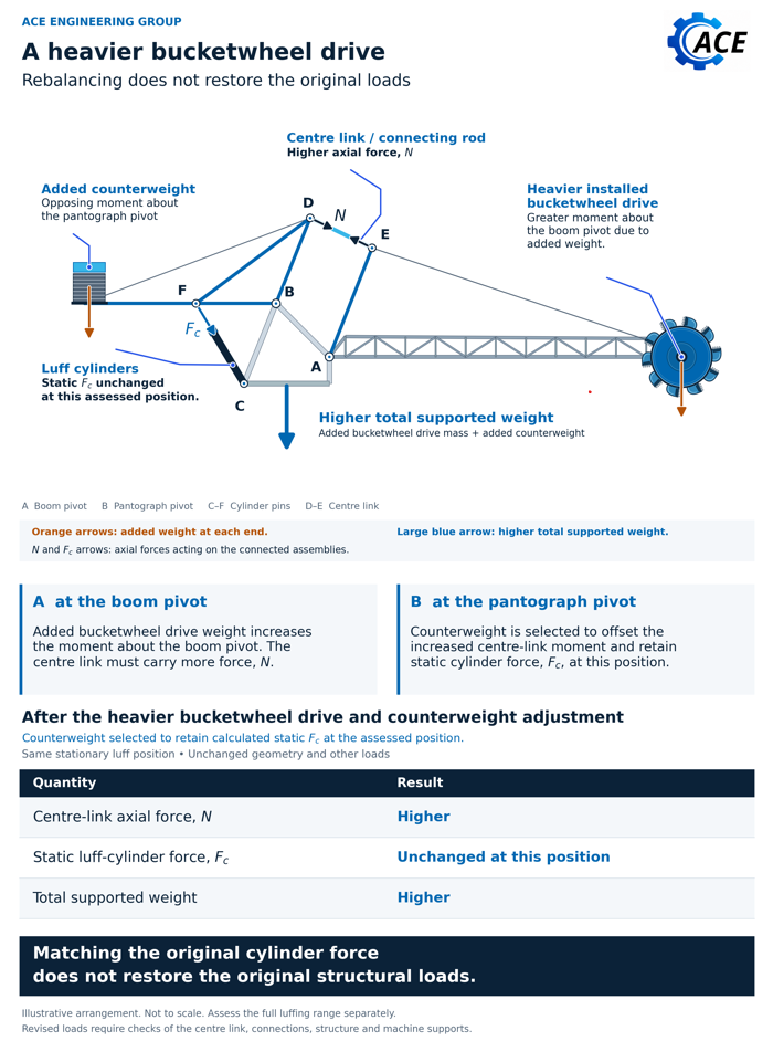
In the pantograph reclaimer considered here, the centre link is the connecting rod between the bucketwheel boom and the separately pivoted counterweight assembly. The illustration compares one stationary luff position, with unchanged geometry and other loads. Its result is specific to that arrangement and those assumptions.
Include the complete installed mass change
The replacement electric bucketwheel drive adds net installed mass in this example. Include the supports and associated additions or removals, together with their centre of gravity locations. The relevant change is the installed arrangement, rather than the drive unit in isolation.
Here, the revised arrangement increases the moment due to weight about the main boom pivot. At the same stationary luff position, with unchanged geometry and other loads, the centre link must carry a higher axial force to balance that increased moment.
Counterweight can restore cylinder force at one position
Suppose the upgrade assessment identifies a counterweight addition. Its opposing moment about the pantograph pivot can offset the increased moment introduced by the centre link. A suitable adjustment may bring the calculated static cylinder force close to its previous value at that position.
The centre link force remains higher. The total supported weight also increases: the machine now carries both the additional installed bucketwheel drive mass and the added counterweight.
- Centre link axial force: higher under the stated comparison.
- Static luff cylinder force: may return to its earlier value at the assessed position.
- Total supported weight: higher because both mass additions remain on the machine.
Matching the original cylinder force does not restore the original structural loads.
Compare the post upgrade trend across the assessed luff range
For the post upgrade luff trend, plot pressure derived cylinder force against boom angle and compare it with the revised prediction. Use equivalent loading and test conditions across the assessed luff range, including the washdown condition and direction of the last movement.
For a conventional single rod cylinder, pressure acts on different effective areas in the two chambers. The ideal net hydraulic force is the cap end pressure multiplied by the full piston area minus the rod end pressure multiplied by the annular area, taking extension as positive. HAWE identifies friction as a reason actual output differs. One chamber pressure alone may therefore misrepresent the force. [1]
Agreement at one position does not establish agreement elsewhere. A familiar trend does not demonstrate the capacity of the centre link, its end connections or the boom. Use the trend as one part of the evidence supporting the revised machine assessment.
Assess drive reactions and follow the load through the machine
The replacement drive mounting needs its own assessment. Include reactions from any increase in permitted operating or peak torque, combined with weight and other applicable loads. A heavier drive does not automatically mean higher torque; establish the proposed drive duty and permitted limits.
Follow the revised loads through the centre link, end connections, boom, slew bearing and its mountings into the supporting structure and travel gear. Include machine stability. How individual support reactions change depends on the revised mass distribution and machine position.
Where the upgrade also changes cylinder arrangements, pressure limits or control settings, assess the luff system and control interfaces together. A satisfactory cylinder force comparison does not close those separate checks.
Define what can be retained and what needs work
ACE uses a whole machine comparison to establish what can be retained, what needs modification and what must be verified. The assessment should identify the affected components and connections, the supporting calculations and any missing information needed to resolve their capacity.
That gives the project team a basis for developing the installation and verification scope before committing to the drive upgrade. Any unresolved assumptions, load cases and commissioning checks should remain visible in the design records.
Practical checks
- Record net installed mass changes, including supports, additions, removals and centre of gravity locations.
- Confirm the actual linkage geometry and the luff positions covered by the comparison.
- Assess the centre link, connections and boom separately from the cylinder force result.
- Compare the measured trend with the revised prediction under equivalent conditions across the assessed luff range.
- Check mounting reactions against the proposed operating and peak torque limits.
- Trace the revised loads into the slew bearing, supporting structure and travel gear, and assess machine stability.
- Record what can be retained, what requires modification and which verification items remain open.
Before installing the heavier bucketwheel drive, trace the revised loads through the machine and verify the capacity of the affected components and connections.
References
1. HAWE Hydraulik SE: Piston: Fluidlexikon